How to connect stm32 to a programmer?
Most STM32 boards are programmed/debugged over SWD (Serial Wire Debug), using tools like ST-LINK, J-Link, or CMSIS-DAP. The wiring is…
How to connect stm32 to a programmer?
Most STM32 boards are programmed/debugged over SWD (Serial Wire Debug), using tools like ST-LINK, J-Link, or CMSIS-DAP. The wiring is simple — then it’s mostly about power, reset, and pin mapping.
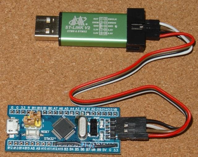
1) Use SWD (recommended)
Minimum wires (works for programming + debugging)
Connect programmer → STM32:
- SWDIO → SWDIO
- SWCLK → SWCLK
- GND → GND (common ground is mandatory)
- VREF / VTref (if available) → 3.3V of the target (lets the debugger sense target voltage)
Strongly recommended extras (improves reliability)
- NRST → NRST (reset line; helps connect when the chip is “stuck”)
- Optional: SWO → SWO (single-wire trace output for ITM printf / tracing)
Typical STM32 debug header (2×5, 1.27 mm “Cortex Debug”)
If your board has the standard ARM 10-pin header, it’s usually:
- SWDIO, SWCLK, GND, VTref, NRST, SWO
If it’s a simple 1×4 header, it often exposes:
- SWDIO, SWCLK, GND, 3V3
2) Pin names on the STM32 (where to wire)
It depends on the STM32 family/package, but common mappings are:
- SWDIO: usually PA13
- SWCLK: usually PA14
- SWO: often PB3 (on many families)
- NRST: dedicated reset pin
(Always confirm with the datasheet or board schematic — some boards remap or don’t expose SWO.)
3) Powering the target: who powers whom?
Two common setups:
A) Target board powers itself (most common)
- You power the STM32 board via USB or external 3.3V/5V regulator.
- Debugger connections: SWDIO/SWCLK/GND + (optional) VTref to 3.3V.
B) Debugger powers the target (sometimes possible)
- Some ST-LINK versions can provide 3.3V, but current is limited.
- Only do this for small targets (no motors, radios, big loads).
- Still connect grounds.
Important: Never connect two different power sources fighting each other.
4) Common connection problems (and fixes)
“No target connected” / cannot connect
Try these in order:
- Ensure GND is connected.
- Connect NRST as well (reset helps a lot).
- In STM32CubeProgrammer or IDE:
- Lower SWD speed (e.g., 100 kHz–1 MHz).
-
Use “Connect under reset” mode.
-
If you configured pins as GPIO accidentally:
- Boot with BOOT0 high (bootloader) or use “under reset” to regain access.
- Check that PA13/PA14 aren’t blocked by board wiring.
Works once, then fails after flashing
Usually:
- You changed clock settings and the chip is unstable.
- You enabled low-power modes or reconfigured debug pins. Fix:
- “Connect under reset”, erase, reflash.
5) If you use UART bootloader instead (no debugger)
Some STM32 parts support the ROM bootloader via UART:
- Set BOOT0 = 1 (and BOOT1 depending on family)
- Reset
- Connect UART TX/RX to a USB-TTL adapter
- Use STM32CubeProgrammer (UART mode)
But for development, SWD is the best.
Quick wiring cheat sheet (ST-LINK ↔ STM32)
- ST-LINK SWDIO → STM32 PA13 (SWDIO)
- ST-LINK SWCLK → STM32 PA14 (SWCLK)
- ST-LINK GND → STM32 GND
- ST-LINK VTref → STM32 3.3V
- ST-LINK NRST → STM32 NRST (recommended)
메타데이터
- post_id
- f35ffb89077f
- slug
- how-to-connect-stm32-to-a-programmer-f35ffb89077f
- url
- https://medium.com/@pqshedy33/how-to-connect-stm32-to-a-programmer-f35ffb89077f
- canonical_url
- https://medium.com/@pqshedy33/how-to-connect-stm32-to-a-programmer-f35ffb89077f
- author_url
- https://medium.com/@pqshedy33
- status
- ok
- fetched_at
- 2026-07-13 10:58:23