Focus ion beam (FIB): Beam spot profile and application implications
Dr. Chengge Jiao, 29 April 2025
Focus ion beam (FIB): Beam spot profile and application implications
Dr. Chengge Jiao, 29 April 2025
A short description
Focused Ion Beam (FIB) systems utilize a central, high-resolution spot for precise material processing. However, the ion beam also exhibits lower-intensity tails extending beyond this central region, which can introduce artifacts during sample preparation. Characterization of the ion beam’s spatial intensity profile is therefore crucial for optimizing FIB milling efficiency. This discussion clarifies the fundamental purpose of a FIB-induced deposition cap layer in the preparation of high-quality Transmission Electron Microscopy (TEM) specimens. Routine monitoring of the ion beam’s profile is essential for maintaining optimal FIB system performance.
FIB 101 — Understanding the ion beam’s spot profile is the foundational step towards effectively utilizing your FIB system.
The most important property of FIB is the individual beam spot, and at the heart of the focused ion beam lies its beam’s profile.
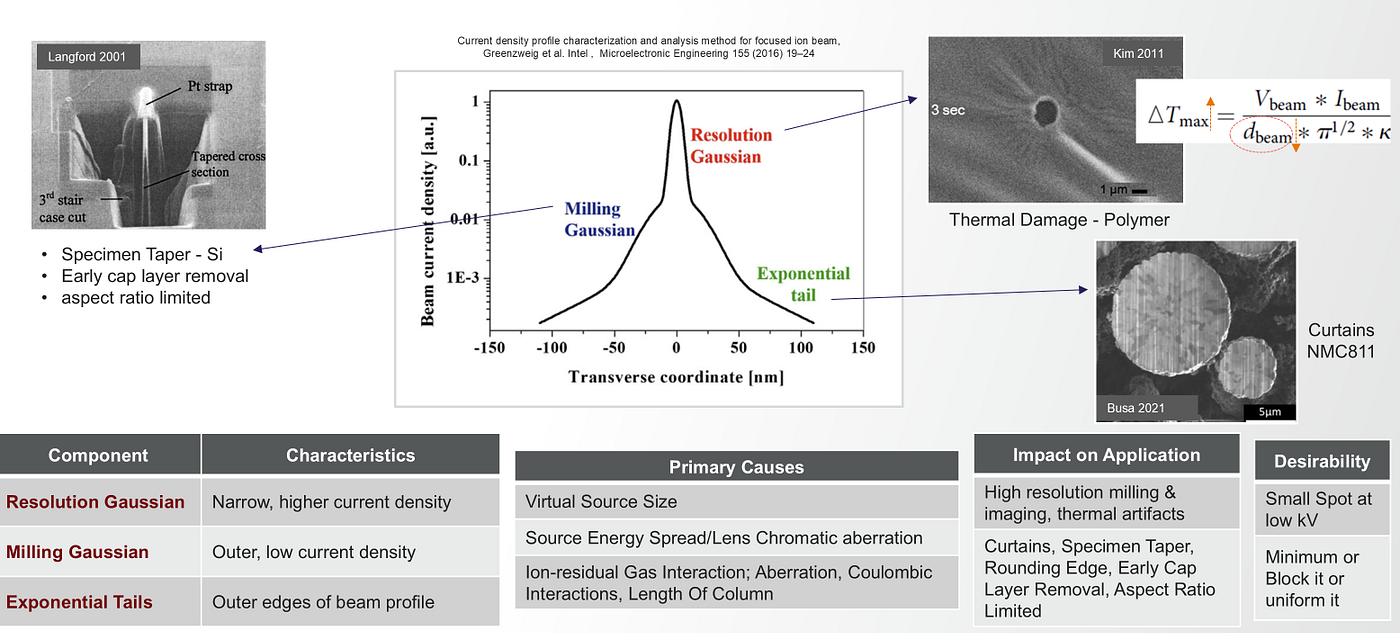
The profile of a focused accelerated ion beam is reported to be Gaussian in shape with large tails. The spot profile has three important components, highlighted in this figure by Greenzweig et al.
First, the Resolution Gaussian — this is the narrow, central part, vital for achieving high-resolution imaging and precise milling. It’s largely determined by the ion source virtual size. However, the beam also exhibits a less desirable, wider Milling Gaussian component. This broader portion carries less current and unfortunately leads to broader milling, primarily due to chromatic aberration arising from the ion source energy spread and secondarily from the spherical aberration of the lenses. Finally, there are the Exponential Tails, this is the Beam outskirts, the low-intensity outer edges of the beam. These tails aren’t ideal as they can cause unwanted sputtering or activate gas precursors outside our intended area, reducing precision and inducing artifacts. The causes are likely a combination of ions colliding with residual gas in the column and the repelling forces between the charged particle ions themselves Coulombic interactions.
Knowing your FIB beam profile has broad implications for sample preparation. For milling applications, a well-defined beam profile enables more precise for TEM specimen preparation and predictable material removal, yielding sharper edge or features, less collateral damage and redeposition contamination. A small beam spot at 30 kV presents a higher risk of ion beam-induced thermal damage, particularly for materials with low thermal conductivity such as polystyrene (0.13 W/m·K), compared to silicon (149 W/m·K) and aluminum (247 W/m·K). During low-energy ion beam cleaning for TEM specimen preparation, it is crucial to utilize a beam spot with minimal beam tails.
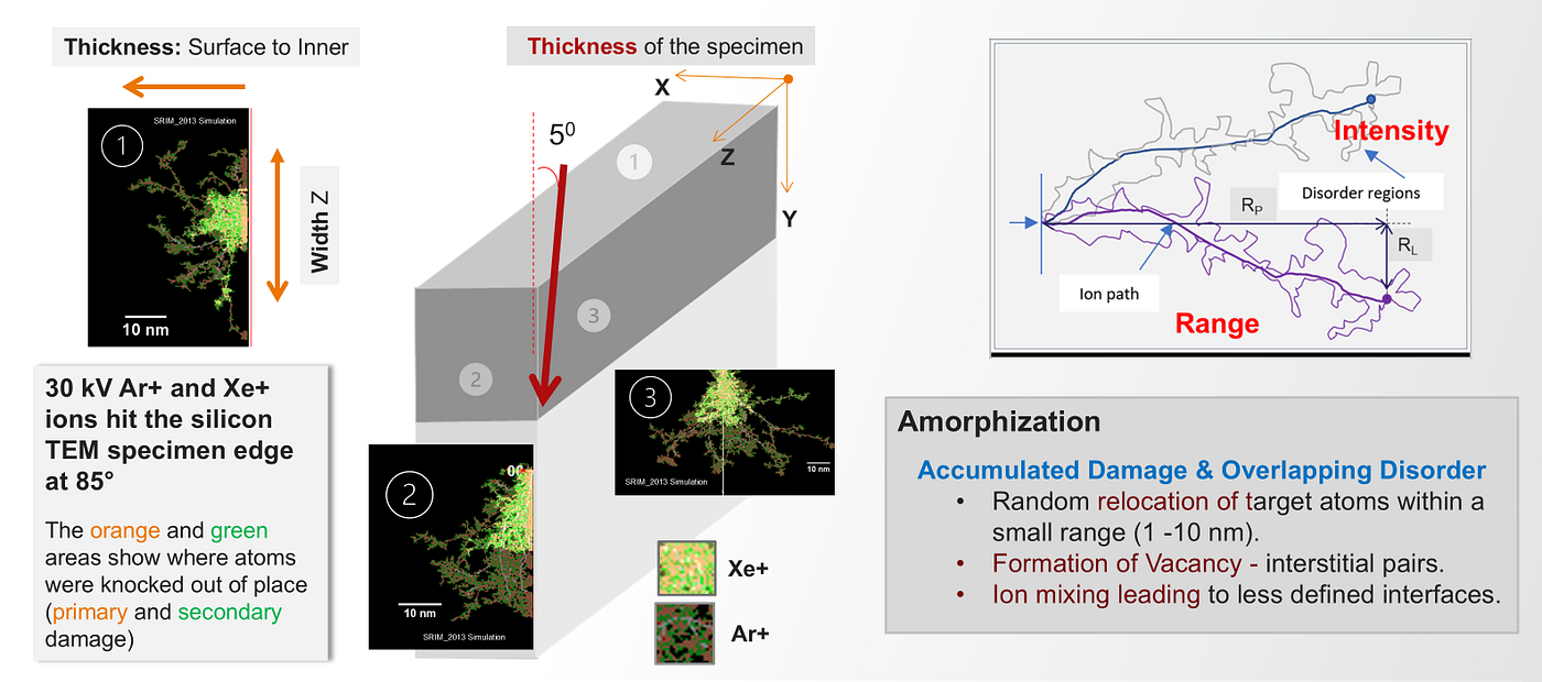
The tails components in combination with the sputter yield dependence on the incident angle of the ion beam results in a cross-section specimen being tapered in profile and produces “water-fall” curtain effects.
To mitigate unwanted effects from beam tails, we can employ a protective cap layer, often deposited using Gas Injection System (GIS) in the FIB system. For this capping to effectively block the beam tails, the deposited layer’s thickness should be comparable to the radius of the beam tail.
In a Ga+ FIB system, a cap layer thickness of approximately 1 to 2 µm is generally sufficient due to the relatively small extent of the Ga+ beam tails.
However, high-current Plasma FIB (PFIB) applications often necessitate a thicker cap layer, typically more than 8 µm because of a much larger beam tails of Xe+ plasma ion beam spot. To mitigate artifacts such as curtaining and redeposition of the cap layer material (commonly Pt or W deposited using a Xe+ ion beam or by gas mixing of Pt+C) during TEM specimen preparation, we recommend the following procedures: (1) Perform Xe+ ion beam induced deposition at lower accelerating voltages of 8 kV. This best practice helps to avoid the encapsulation of Xe gas bubbles within the cap layer. (2) Thoroughly remove the majority of the cap layer at 5 kV before proceeding with lower kV cleaning steps at 2 kV and 1 kV. This strategy minimizes the risk of Pt or W redeposition onto the sidewalls of the TEM specimen.
Minimizing beam tails is particularly critical gas assisted milling. The low-intensity outer regions of the beam can unintentionally activate adsorbed precursor molecules outside the intended processing area, leading to undesired material removal or deposition and reducing FIB milling accuracy.
Periodic characterization of the ion beam profile via spot burns is a good practice for monitoring the operational health and performance of both Ga+ and Xe+ FIB systems. This proactive approach enables timely adjustments and maintenance, ensuring consistent and reproducible outcomes in imaging and milling processes. Furthermore, reliable profile characterization is invaluable for the development of advanced FIB sources and columns, providing a quantitative method to assess performance and optimize ion optics.
Summary
Understanding the FIB beam profile, typically Gaussian with extended tails, is fundamental to FIB performance. The profile includes a narrow resolution component, a broader milling component affected by aberrations, and low-intensity tails causing unwanted sputtering. Cap layers can mitigate tail effects, requiring specific thicknesses and careful removal during TEM specimen prep to avoid artifacts. Characterizing the beam profile is crucial for optimizing milling precision and ensuring consistent FIB system operation.
Reference
Microelectronic Engineering 155 (2016) 19–24, Yuval Greenzweig, Yariv Drezner, Shida Tan, Richard H. Livengood, Amir Raveh
Ultramicroscopy 111 (2011) 191–199, Suhan Kim, Moon Jeong Park, Nitash P Balsara, Gao Liu, Andrew M Minor
J. Vac. Sci. Technol. A19, 2186 (2001), Richard Langford and A. K. Petford-Long
Electrochimica Acta 366 (2021) 137358, Chiara Busà, Meltiani Belekoukia, Melanie J. Loveridge
메타데이터
- post_id
- f3b8bd5e9e6b
- slug
- focus-ion-beam-fib-beam-spot-profile-and-application-implications-f3b8bd5e9e6b
- url
- https://medium.com/@cgjiao/focus-ion-beam-fib-beam-spot-profile-and-application-implications-f3b8bd5e9e6b
- canonical_url
- https://medium.com/@cgjiao/focus-ion-beam-fib-beam-spot-profile-and-application-implications-f3b8bd5e9e6b
- author_url
- https://medium.com/@cgjiao
- status
- ok
- fetched_at
- 2026-06-26 21:52:29