Trilateration Looked Perfect on Paper. Here’s Why It Broke in Production
Part 1 of 2 — A breakdown of why analytic trilateration fails on noisy FTM distance measurements, and what synthetic test data won’t tell…
Trilateration Looked Perfect on Paper. Here’s Why It Broke in Production
Part 1 of 2 — A breakdown of why analytic trilateration fails on noisy FTM distance measurements, and what synthetic test data won’t tell you.
Indoor positioning is one of those problems that looks like geometry until you ship it. Then it turns out to be statistics.
I learned this the expensive way while writing the location-calculation endpoint for a patient-tracking system. The architecture was straightforward on paper: ESP32-C6 beacons measured distance to fixed anchors using IEEE 802.11mc Fine Time Measurement (FTM), the beacons forwarded those measurements to a Vapor server, and the server was supposed to fuse them into a single 2D coordinate the iOS dashboard could render on an indoor map.
My first implementation used classical trilateration. It passed every synthetic test I threw at it. It also reported, in live testing, that beacons inside the building were standing in walls, in hallways they couldn’t physically reach, and occasionally several meters outside the building entirely.
This post is about why the textbook approach broke. Part 2 is about what replaced it.
The input: what FTM actually gives you
FTM is a Wi-Fi feature standardized in 802.11mc. Two stations — in our case a beacon (FTM Initiator) and an anchor (FTM Responder) — exchange a sequence of timestamped frames. The round-trip time between them, divided by two and multiplied by the speed of light, yields a distance estimate in meters.
Per measurement, the server receives a payload roughly like this:
struct FTMMeasurementDTO: Content {
    let anchorMac: String      // MAC of the anchor that responded
    let distanceMeters: Double // RTT-derived distance
    let rttNanoseconds: Int    // Raw round-trip time
    let rssi: Int              // Received signal strength
}
With multiple anchors per floor at known positions, the classical move is to combine three or more distance measurements into a single 2D position. That’s trilateration.
The textbook approach
Given three anchors at Ai=(xi,yi)Ai=(xi,yi) and measured distances riri from the beacon, the unknown position (x,y)(x,y) satisfies a system of three nonlinear equations:

Subtracting the first equation from the second and third linearizes the system. The quadratic terms cancel, leaving a 2×2 linear system you can solve directly:

A determinant check guards against the degenerate case where the three anchors are collinear (the determinant is zero) and the inversion is undefined.
Translated to Swift:
private func calculateTrilateration(
    measurements: [FTMMeasurementDTO],
    anchors: [Anchor]
) -> PreciseLocationDTO? {
    guard measurements.count >= 3 else { return nil }

    let pairs = measurements.prefix(3).compactMap { m -> (Anchor, Double)? in
        anchors.first(where: { $0.macAddress == m.anchorMac })
            .map { ($0, m.distanceMeters) }
    }
    guard pairs.count == 3 else { return nil }

    let (a1, r1) = pairs[0]
    let (a2, r2) = pairs[1]
    let (a3, r3) = pairs[2]

    let A = 2 * (a2.positionX - a1.positionX)
    let B = 2 * (a2.positionY - a1.positionY)
    let C = r1*r1 - r2*r2
          - a1.positionX*a1.positionX + a2.positionX*a2.positionX
          - a1.positionY*a1.positionY + a2.positionY*a2.positionY
    let D = 2 * (a3.positionX - a2.positionX)
    let E = 2 * (a3.positionY - a2.positionY)
    let F = r2*r2 - r3*r3
          - a2.positionX*a2.positionX + a3.positionX*a3.positionX
          - a2.positionY*a2.positionY + a3.positionY*a3.positionY

    let denominator = A * E - B * D
    guard abs(denominator) > 0.0001 else { return nil }  // collinear anchors

    let x = (C * E - B * F) / denominator
    let y = (A * F - C * D) / denominator

    return PreciseLocationDTO(x: x, y: y, z: nil)
}
The derivation is clean. The implementation is short. Against synthetic test cases — three anchors at known positions, distances computed by hand — it returned the target coordinates to six decimal places.
I committed it with confidence. That confidence didn’t survive contact with a real room.
Where it fell apart: the FTM noise floor
The thing synthetic tests cannot reproduce is that FTM distance measurements in a real indoor environment are substantially noisier than the algorithm assumes.
A few sources of that noise:
- Multipath propagation. Wi-Fi signals reflect off walls, ceilings, metal surfaces, and furniture. The receiver sees multiple arrivals of the same signal at slightly different times, and the RTT estimate gets pulled toward whichever path the chip’s correlator latches onto.
- Hardware timestamp resolution. ESP32-C6’s FTM timestamps are nanosecond-precision in theory, but real chips have measurable jitter and calibration offsets that translate directly into distance error at roughly 0.3 meters per nanosecond.
- Environmental interference. Co-channel Wi-Fi traffic, Bluetooth devices, microwaves, and even fluorescent lighting affect the carrier in ways that show up as distance noise.
- Non-line-of-sight conditions. A wall, a wooden door, or a human body between the beacon and the anchor adds propagation delay. The signal still arrives, but it arrives as though the path were longer than it actually is.
The empirical result for our deployment: distance readings to a stationary beacon hopped by ±30 to ±50 centimetersbetween consecutive measurements. Not in adversarial conditions. In a normal indoor room.
Why analytic trilateration is fragile under noise
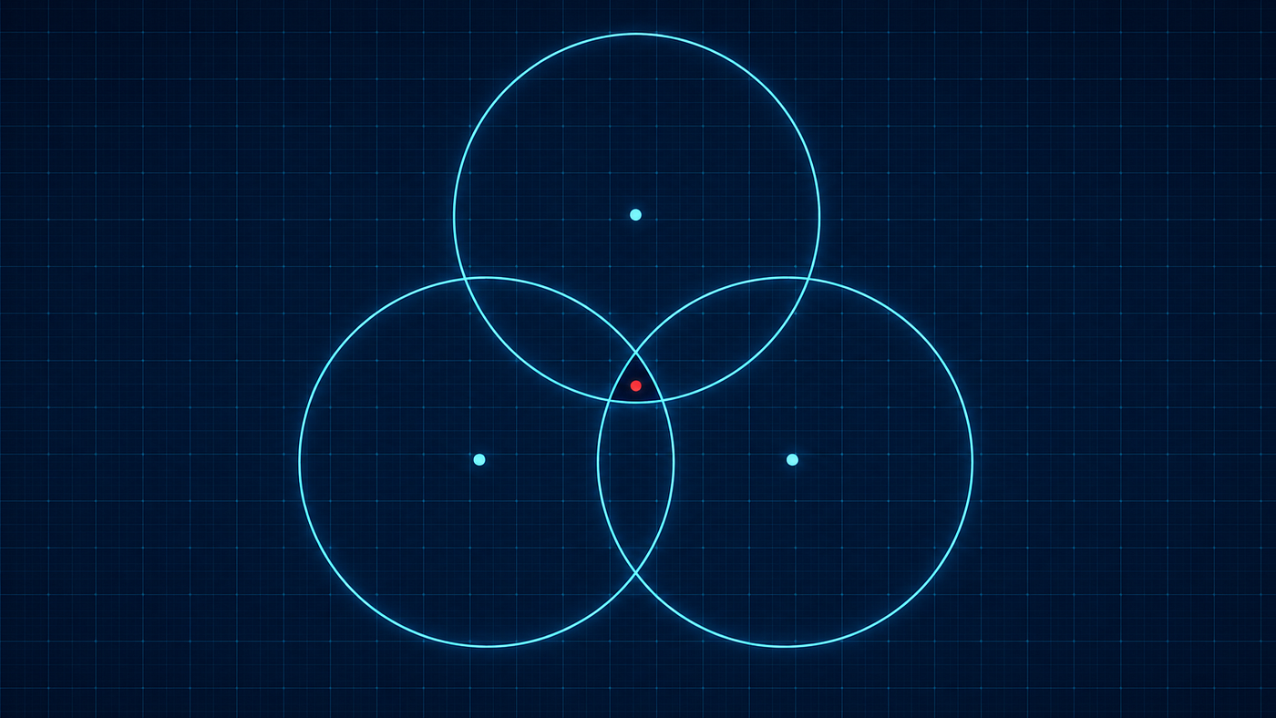
Trilateration’s geometric interpretation is three circles intersecting at a point. With perfect measurements, those circles meet at exactly one location. With noisy measurements, three things can go wrong, and all of them did:
1. The circles fail to intersect at all. If the true distances were (3.0, 3.0, 3.0) but the measurements were (2.7, 3.4, 3.1), the three circles form a small “dirty triangle” of pairwise intersections rather than meeting at a single point. The linear system still has a solution — but that solution is a point outside the triangle, often dramatically far from the beacon’s true position.
2. The 2×2 matrix approaches singularity. When the anchors are nearly (but not exactly) collinear, the determinant (AE — BD) becomes very small. Small numerator/denominator errors get amplified into wild swings in (x, y). The estimate oscillates by meters between consecutive frames even when the beacon hasn’t moved.
3. The output is not bounded by the geometry. Nothing in the closed-form solution constrains (x, y) to lie inside the convex hull of the anchors, or inside the building at all. A bad set of measurements can — and frequently did — return coordinates several meters past the outer wall.
The fundamental issue is that trilateration treats the input as ground truth and propagates whatever error is in those inputs through an unstable computation. Small input perturbations produce large output perturbations. In numerical-analysis terms, the problem is ill-conditioned in the regime where my measurements actually lived.
What mitigations didn’t fix
The obvious response to noisy inputs is to clean the inputs. I tried the standard moves:
- RSSI-based filtering. Drop measurements with received signal strength below a threshold, on the assumption that weak signals correlate with bad ranging. The output got marginally better. It still drifted through walls.
- Temporal smoothing. Average the last five readings per anchor before feeding them into the formula. This reduced frame-to-frame jitter but introduced lag — and noisy averages of noisy measurements are still noisy.
- Consistency thresholds. Require that the three distance readings be within 10% of each other across two consecutive frames before computing a position. This produced very few false positions and also very few positions of any kind. Coverage collapsed.
- Kalman filtering on the distance values themselves. The embedded team was already doing this on the beacon side, predicting the next distance from the previous one and blending the prediction with the new measurement. It tightened the per-anchor noise distribution but didn’t change the fundamental conditioning of the trilateration step.
None of these were wrong, individually. They just couldn’t reach the actual problem.
The diagnosis
After enough iteration on input cleanup, the diagnosis became clear: the algorithm was solving the wrong formulation of the problem.
Trilateration as a closed-form solution assumes that “three circles intersect at a point” is the question to answer. With sensor input, that’s the wrong question. The right question is: given three noisy distance readings, what is a reasonable estimate of the beacon’s position? Those formulations sound similar. They are not the same. The first has a unique exact answer when the inputs are clean and an unstable approximate answer when they’re not. The second has no exact answer at all — only better and worse estimators, judged by criteria like bias, variance, and worst-case behavior under noise.
A precise algorithm gives the right answer when the inputs are clean. A robust algorithm refuses to give a catastrophically wrong answer when the inputs are dirty. These are different properties, and they are usually in tension.
Trilateration is the first kind. The use case — locating beacons on an indoor floor using consumer-grade Wi-Fi ranging — needed the second kind.
메타데이터
- post_id
- f4a97072aec2
- slug
- trilateration-looked-perfect-on-paper-heres-why-it-broke-in-production-f4a97072aec2
- url
- https://medium.com/@euijjang97/trilateration-looked-perfect-on-paper-heres-why-it-broke-in-production-f4a97072aec2
- canonical_url
- https://medium.com/@euijjang97/trilateration-looked-perfect-on-paper-heres-why-it-broke-in-production-f4a97072aec2
- author_url
- https://medium.com/@euijjang97
- status
- ok
- fetched_at
- 2026-07-11 01:06:15