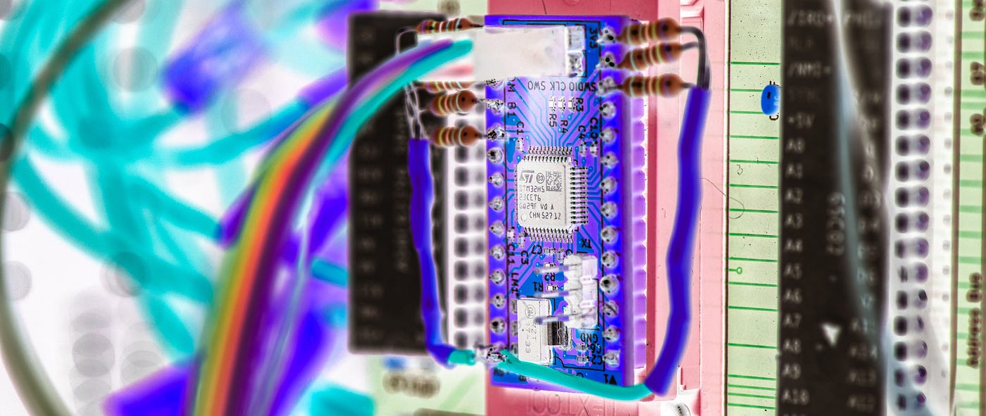
McROM: A microcontroller-based ROM emulator for a homebrew computer
EEPROMs are all very well, but they’re not convenient. Could a microcontroller do the job faster and with less fuss? Maybe.
MICROCONTROLLERS
McROM: A microcontroller-based ROM emulator for a homebrew computer
EEPROMs are all very well, but they’re not convenient. Could a microcontroller do the job faster and with less fuss? Maybe.
This is part of an ongoing pursuit of laziness. Doing the same thing over and over is tedious. We need to cut that out.
A good example of a repetitive task is flashing ROM code to an EEPROM for your homebrew 8-bit computer. Or, to be more precise, my homebrew 8-bit computer, the 65C02-based Zolatron.

The Zolatron 65C02-based homebrew computer.
Every time I needed to test (or use) a change made to the ROM code I would have to power off the Zolatron, pull the EEPROM from its socket, put it in the programmer device, run the build script, remove the chip from the programmer, place it back in the Zolatron and power on again. Gah!
That led me to explore alternatives to EEPROMs. One idea was to use a microcontroller as a ROM. You’d upload the ROM code to the MCU’s flash along with a small program that would watch the signals that tell the ROM when it needs to be active, at which point it would read the address bus, look up the relevant byte from the ROM code and send it out on the data bus.
This is not an original idea. It has been done many times, most notably, perhaps, with the excellent OneRom project. I have two of these devices but, at the time I started this project, the OneRom didn’t support emulation for the 28C256 EEPROM (that has since changed). And besides, as good as the hardware and software for the OneRom are, it still represents an off-the-shelf solution, and you don’t learn anything from that. Nor do you have the joy of constant defeats and disappointments that you get with creating something yourself.
Do it yourself
And so I decided I would have a go myself. At first, I toyed with the idea of using the ATmega4809 microcontroller. It has enough GPIO pins to accommodate the 14 address bus lines, eight data bus lines and the two other signals (chip enable and output enable) that need to be managed. And I am familiar with, and enjoy, the AVR 8-bit microcontroller ecosystem.
But it soon dawned on me that, even at 20MHz, the ATmega chip was not going to be able to provide the responsiveness that even a slothful 1MHz 65C02 computer needs. And so I knew the time had finally come to hurl myself towards the steep face of yet another learning curve and do battle with a better class of microcontroller — the STM32.
This is an ambitious project for a first foray into the STM32 domain. Most people — sensible people — are content with blinking an LED as an introduction to a new programming world. But not me. I’ve blinked enough LEDs in my life. It was time to aim high.
But first, what should we call it? What is an appropriate name for a microcontroller-based ROM? The obvious answer is: McROM.
This is the first of a short series of articles because there’s a lot of ground to cover, including designing the PCB, testing the proof of concept, writing code for the STM32 and running it in the Zolatron.
The PCB
Let’s start with the board. The secret to this solution is the code. But you need to have something on which to run it, and that something has to fit into the target 6502 machine.
I could have gone some way towards a proof of concept with a Nucleo development board. But I decided, what the hell — I’ll spin up a PCB with the precise MCU I want. Because, in essence, it’s a simple breakout board, albeit with a couple of major constraints, one of which would cause a few programming headaches.

Schematic for the board I had fabbed. I wouldn’t do it this way again, but that’s another story.
I wanted it to have the same pinout and physical footprint as an AT28C286, which is the EEPROM chip I chose for the Zolatron. The McROM needed to be a drop-in replacement, but one I could re-program in situ. So the STM32 sits on a board cosplaying as an EEPROM.
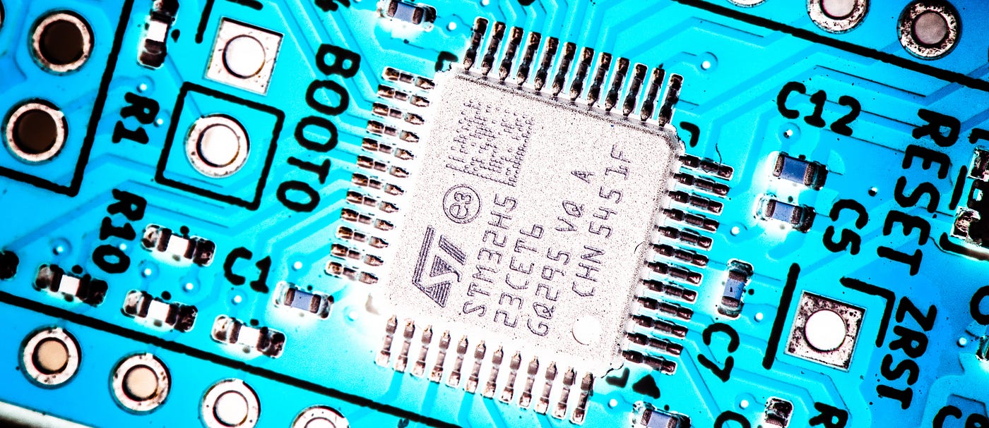
Another issue is that STM32s are 3.3V devices, whereas the Zolatron’s logic is all at 5V. Coupled with the need for enough flash and RAM space to accommodate the 16KB ROM data plus code and enough grunt to keep up with the host machine I was ultimately led to the STM32H523CET6.
If you’re new to STM32s, their long and convoluted model names can be intimidating. The key bit here is that ‘H5’, which denotes a family of high-performance MCUs. This model screeches along at 250MHz using its internal oscillator, which is nice. The ‘5’ tells us it uses an ARM Cortex‑M33F core.
The ‘C’ indicates it’s a 48-pin package, which means lots of lovely GPIOs. Crucially, most of the GPIOs on this chip are 5V-tolerant, which is what made the whole idea possible. Level-shifting all the data, address and control lines would have been a nightmare.
The ‘E’ means the MCU has 512KB of flash storage, which is far more than I need, but gives plenty of room for future development. And the ‘T’ bespeaks a conveniently compact QFP package. Not revealed by the name is the 272KB of static RAM.
At about €5.50 a pop from Mouser, that’s a hot-rod of a microcontroller for a Lada price.
Not all in a row
Like many a chip, however, the STM32H523CET6’s GPIO pins for any given port are not all contiguous — or, to put it another way — pins PA0 to PA7 are not all in a neat little row, and much the same goes for ports B and C.
This posed challenges for routing between the GPIOs and the data and address bus pins on the (virtual) 28C256, which have their own brand of chaos. The STM32 chip sits in the middle of the 28C256’s footprint with traces fanning out to the pins. And I had no choice about the pin assignment of the 28C256.
In the end, with space so constrained on the board, I often just had to run each 28C256 pin to the nearest STM32 GPIO. The pin assignment ended up looking like this:

The pin assignments of the STM32H523CET6 on the left and the footprint of the AT28C256 EEPROM on the right.
(By the way, you’ll notice that some of the pin assignments on the STM32 are labelled as GPIO_Input or GPIO_Analog. These are, in fact, unused pins, but setting them as inputs reduces power draw and noise and is better than leaving them undefined.)
For programming, I included a 2x3 pin header accommodating the three SWD pins, reset, +3.3V and GND. I’d read somewhere that the SWD lines should have 100Ω inline resistors (I assume that’s to reduce signal reflections or limit current or something equally clever).
The +3.3V power for the MCU is provided via an LM1117 regulator, itself supplied by the +5V pin on the 28C256 pinout. In other words, the power is coming from the host computer. Even in SMD format, the LM1117 turned out to be an uncomfortably large part for such a small board, but I squeezed it in there somehow.
The same goes for the three-pin header for the serial port. As I had the pins available for the STM32’s default UART, I figured, why not throw a serial port in there. It’s something I do a lot with microcontroller projects. You can do a lot of debugging over serial. In this case, however, it was a mistake, though not a disaster.
Small parts
Due to space constraints, most of the passives — ie, resistors and capacitors — are in 0402 (1005 metric) packages. These are much smaller than I’d contemplate even for oven-based reflow soldering (my go-to method for surface mount work). Fortunately, PCBWay once more stepped up to the plate and offered free PCB fabrication, including sourcing SMD parts and assembly, as a way of supporting this publication. Phew!

The board as it arrived from PCBWay and before I soldered on headers. Some of those passive devices are tiny.
The resulting boards are gorgeous, especially in the fancy yellow solder mask I’d selected. The small board size meant that I’d really pushed the lower limits for the text size on the silkscreen, but it’s all very readable (especially with a magnifying glass). All the soldering, too, was very neat but robust — which turned out to be a significant detail, as we’ll see in a moment.
The next stage was to write the firmware code. But I didn’t want to jump right in by having a stab at the complete solution because I knew that, when it didn’t work, figuring out the fault would be that much more complicated.
So I slapped one of the boards into a breadboard and wrote something equivalent to the immortal blinky sketch.
Alas, when time came to upload the firmware to the MCU, it refused to go. The upload tool just sat there and insisted there was no STM32 device connected. No amount of pointing to the breadboard would convince it.
Scouring the interwebs eventually convinced me that the 100Ω inline resistors I’d placed on the lines going to the SWD header were causing the problem. (It later turned out they weren’t.) So I figured that I’d simply remove them and short the pads with some solder.
This was when I discovered the high quality of PCBWay’s soldering and solder masks. The tiny blighters did not come off the board without a fight. Then, when I tried blobbing on solder, it truculently insisted on separating into two, unconnected blobs instead of one big one because the solder mask was doing its job excessively well. I ended up using short bits of wire (the cut-off remains of through-hole resistor legs) to bridge the pads. It wasn’t easy.
The result was two boards without inline resistors to SWDIO, SWDCLK and SWD0. There were also two casualties — boards that suffered soldering ‘episodes’. We mourn their loss. One of the reconfigured yet working boards would later be rendered useless in a programming incident that left the STM32 MCU in an unrecoverable state.
Luckily, the first board, which I hadn’t modified but which had been giving me programming issues, started co-operating again. So of the five boards supplied by PCBWay, two currently remain in service.
The jury’s still out on whether those resistors needed removing at all. The boards seem to work either way. What the original problem was, I have no idea.
The toolchain
A quick note on the toolchain I’m using. As detailed in a previous article, I program in VS Code with the STM32Cube extensions. This setup also provides a good debugging enviroment.
Some of the steps, however, involve command line tools such as arm-none-eabi-objcopy, arm-none-eabi-size, Ninja and, for the actual upload, STM32_Programmer_CLI.
I’m not going to go into detail here about installing and using these tools, but they will crop up in later sections. So let’s turn our attention to software.
Including the ROM
In effect, there are two pieces of software — the ROM code for the 6502 processor and the firmware for the STM32. We need to embed the former into the latter. And my ultimate aim is that the entire process is controlled by a single shell script. Whenever I make a change to the ROM code, I run the script and it:
- Assembles the 6502 assembly code into a ROM binary, called
rom.bin. - Copies that binary to a number of places, including the root directory for the McROM project.
- Converts
rom.binto an object file that can be linked into the STM32 code. - Compiles the STM32 firmware.
- Flashes the new version of the firmware to the McROM board, which never leaves the snuggly confines of the still-running Zolatron.
Assembling the 6502 code is something I’m already doing with a separate shell script. In the days to come, that process will be incorporated into a single script that does all the stages, but let’s not worry about that now.
The rest of what’s about to happen depends on a few variable settings, so let’s get those sorted. I have this at the top of the STM32 build script:
ROM_BINARY="rom.bin"
LINKER_SCRIPT="STM32H523xx_FLASH.ld"
BUILD_DIR="build_linux"
TARGET_NAME="McROM"
ABS_PATH=$(pwd)
Obviously, this is all dependent on my specific setup, but you get the drift. The linker script, STM32H523xx_FLASH.ld is created by STM32CubeMX but we will have to mess with it a little.
Now, about that object file. Originally, I had the 6502 build script create rom.o so that it was always updated whenever I made changes to the ROM code. Then I moved the process to the STM32 build script with this command:
arm-none-eabi-objcopy -I binary -O elf32-littlearm -B arm \
        --rename-section .data=.rom_image \
        "$ROM_BINARY" "$BUILD_DIR/rom.o"
By default, it would put the data into a section cunningly labelled .data. But here we're renaming that section for reasons that will become apparent later.
In any case, there’s still a better way to do it, but we’ll get to that in a moment.
Linking the ROM object
We have to tell the project to link the rom.o code into our STM32 project. In the root folder of the project is that STM32H523xx_FLASH.ld file. The exact name depends on the target device. This is where we need to make the change. Don't be misled into changing the file of the same name in the build/Debug or build/Release folder. That is a copy of the file in the root folder made during compilation and gets overwritten each time you build the project.
We need to add a new section. Towards the top of the file, where it probably says something like…
MEMORY
{
  RAM    (xrw)    : ORIGIN = 0x20000000, LENGTH = 272K
  FLASH   (rx)    : ORIGIN = 0x8000000,  LENGTH = 512K
}
…we add a line to create space for the ROM data:
MEMORY
{
  RAM    (xrw)    : ORIGIN = 0x20000000, LENGTH = 272K
  FLASH   (rx)    : ORIGIN = 0x8000000,  LENGTH = 512K
  ROM_DATA (r)    : ORIGIN = 0x08060000, LENGTH = 64K /* High end of Flash */
}
It’s not mandatory that you create the ROM_DATA memory block. You could just add the ROM data to the FLASH memory block—that’s where it’s going anyway. But there are good reasons for assigning it its own place to live.
One is safety: if your code should grow (unlikely in this context, but let’s not limit ourselves to one application) this approach prevents your code from growing so large that it accidentally bleeds into the ROM data. The linker will give you an error if the code hits that boundary.
The other reason is organisation: It lets you place the ROM data at a specific, predictable address (like the very start of a specific flash sector), which is helpful if you want to update the ROM data later — perhaps via UART — without re-flashing the whole program.
Next, down in the SECTIONS part of the file (I put this just after the .rodata section) we add a new section:
/* ROM DATA */
.rom_section :
  {
    . = ALIGN(4);
    _rom_bin_start = .;
    KEEP(*( .6502_rom_section ))
    . = ALIGN(4);
    _rom_bin_end = .;
    _rom_bin_size = . - _rom_bin_start;
  } > ROM_DATA
The KEEP keyword protects the data from Link-Time Optimisation (LTO) or garbage collection (--gc-sections). Without KEEP, if the linker notices that no code in main.c explicitly references the address _rom_bin_start, it might think the data is unused and could delete it to save space.
Note also the .6502_rom_section. You could use something like:
KEEP(*(.data .data*))This will, in effect, grab data from whatever .data sections in the object files haven't already been used and stuff it into the section we defined earlier (ROM_DATA). It's crude but will work.
Essentially what happens during the linking process is that the linker goes through any object files you specify in the order that you list them. In this case, the object files are main.o, stm32h5xx_it.o, and rom.o. The linker then processes the script from the top and the first match wins.
Each time it gets to a .data section in an object file, it will take the data found there and put it into the assigned part of memory (FLASH, ROM_DATA etc).
When it gets to the .rom_sectionblock, if it sees the instruction *(.data .data*), with the wildcard meaning 'from all remaining files', it will put as much data into ROM_DATA as it can, no matter where it comes from.
This should work. But by creating a specific ROM_DATA part of memory and using KEEP(*( .6502_rom_section)) to specify that we put there only data that comes from a section labelled .6502_rom_section we keep everything separate and cleanly delineated.
CMake magic
You might be wondering where this .6502_rom_section comes from. The answer is a little CMake magic.
In the project root folder is a file called CMakeLists.txt. Again, STM32CubeMX creates this for you whem you select CMake as the toolchain. Here's the entire file for my project:
cmake_minimum_required(VERSION 3.22)
# Setup Project
project(McROM C ASM)

set(CMAKE_C_STANDARD 11)
set(CMAKE_EXPORT_COMPILE_COMMANDS TRUE)

# CREATE THE TARGET
add_executable(${CMAKE_PROJECT_NAME})

# Add the CubeMX subdirectory
add_subdirectory(cmake/stm32cubemx)

# ------ ROM STUFF -------------------------------------------
# Handle the ROM binary
set(ROM_BINARY "${PROJECT_SOURCE_DIR}/rom.bin")
set(ROM_OBJECT "${CMAKE_CURRENT_BINARY_DIR}/rom.o")

add_custom_command(
    OUTPUT "${ROM_OBJECT}"
    COMMAND arm-none-eabi-objcopy -I binary -O elf32-littlearm -B arm
            --rename-section .data=.6502_rom_section
            "${ROM_BINARY}" "${ROM_OBJECT}"
    DEPENDS "${ROM_BINARY}"
    VERBATIM
)

# Add custom objects and libraries to the target
target_sources(${CMAKE_PROJECT_NAME} PRIVATE "${ROM_OBJECT}")
# -----------------------------------------------------------

target_include_directories(${CMAKE_PROJECT_NAME} PRIVATE
    "$ENV{HOME}/Dev/Dev-STM/ms_stm32lib/Inc"
)
Everything in the ROM STUFF section consists of settings I've either added or edited.
We start by setting up a couple of variables. The custom command creates our rom.o file. But note that DEPENDS "${ROM_BINARY}" entry. By making the rom.bin file a dependency, CMake now knows that we need to recompile the STM32 code every time rom.bin changes. Without this, if we made changes to the ROM code but no changes to the STM32 code, the compiler would think there's nothing to be done and would skip compilation.
Adding labels
Let’s get back to that STM32H523xx_FLASH.ld file. You'll see _rom_bin_start and _rom_bin_end labels bracketing the instructions about where to put the data. These are critical because they provide a way for us to hook into the ROM code from our STM32 C code.
These labels are embedded in the object file and they are created automatically by arm-none-eabi-objcopy. But without the lines we mentioned above, it may not give you the labels you want. Depending on platform and tools, those labels can be long and include the full path to the project. To see what labels were created without the specific _rom_bin_start = .; and _rom_bin_start = .; directives, I built the object file and used:
nm rom.oThe labels I got were:
00004000 D _binary__Users_smd_Dev_Dev_STM_McROM_rom_bin_end
00004000 A _binary__Users_smd_Dev_Dev_STM_McROM_rom_bin_size
00000000 D _binary__Users_smd_Dev_Dev_STM_McROM_rom_bin_start
That inclusion of the full path could cause problems with our code if we move the project, say to another machine. That’s why we’ve manually added labels of our own. Now, we can access the ROM data within the C code by creating extern byte array variables:
/* Linker symbols */
extern const uint8_t _rom_bin_start[];
extern const uint8_t _rom_bin_end[];
Being arrays, these are, of course, pointers — one to the start of the ROM data and one to the end. We want the latter to do some simple maths later.
And finally, we flash the firmware to the chip with:
STM32_Programmer_CLI -c port=swd mode=UR -w "$TARGET_NAME.elf" 0x08000000 -v -rstThere’s a little bit more to the build script (which is called build_linux.sh for reasons), but you can see the thing in all its glory on the McROM repo (pro tip: choose the dev branch).
All we need now is some STM32 code to build, but we’ll leave that for the next part. In future articles we’ll also look at how I built a proof of concept test rig and finally got the whole thing (mostly) working.

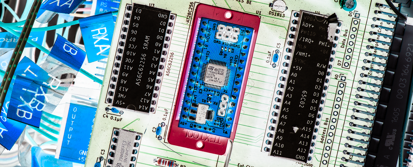
The McROM board taking the place previously reserved for an EEPROM on the Zolatron’s main processor board.
*Steve Mansfield-Devine is a freelance writer, tech journalist and photographer. You can find photography portfolio at Zolachrome, buy his books and e-books, or follow him on Bluesky or Mastodon.*
Or you can buy Steve a coffee — it helps keep these projects going.
메타데이터
- post_id
- f781eef353e4
- slug
- mcrom-a-microcontroller-based-rom-emulator-for-a-homebrew-computer-f781eef353e4
- url
- https://medium.com/machina-speculatrix/mcrom-a-microcontroller-based-rom-emulator-for-a-homebrew-computer-f781eef353e4
- canonical_url
- https://medium.com/machina-speculatrix/mcrom-a-microcontroller-based-rom-emulator-for-a-homebrew-computer-f781eef353e4
- author_url
- https://medium.com/@mansfield.devine
- status
- ok
- fetched_at
- 2026-06-14 11:28:49