Connecting Isolated Networks: Inter-VLAN Routing with Router-on-a-Stick | Homelab #2
In my previous article, we successfully isolated the Accounting and IT departments using VLANs to increase security. However, in real-world…
Connecting Isolated Networks: Inter-VLAN Routing with Router-on-a-Stick | Homelab #2

In my previous article, we successfully isolated the Accounting and IT departments using VLANs to increase security. However, in real-world networks, these separate departments often need to communicate with each other in a controlled way. In this article, I will show you how I connected these two isolated networks using a Cisco 2911 Router. We will explore the Router-on-a-Stick (RoaS) concept and configure subinterfaces via the Cisco CLI to enable Inter-VLAN Routing.
If you have any intention to apply this exercise, complete ***the first homelab exercise of mine***.
Selecting the Router
Go to the Routers category from the device menu in the bottom-left corner of Cisco Packet Tracer. You will see many models there (such as 4331, 2901, 2911, etc.).
For this scenario, the Cisco 2911 Router is the most ideal and stable model because it comes with built-in GigabitEthernet ports.
Why 2911? It has 3 default GigabitEthernet interfaces (g0/0, g0/1, g0/2). These ports are perfect for simulating high-speed connections (uplinks) between switches and preventing network traffic congestion.


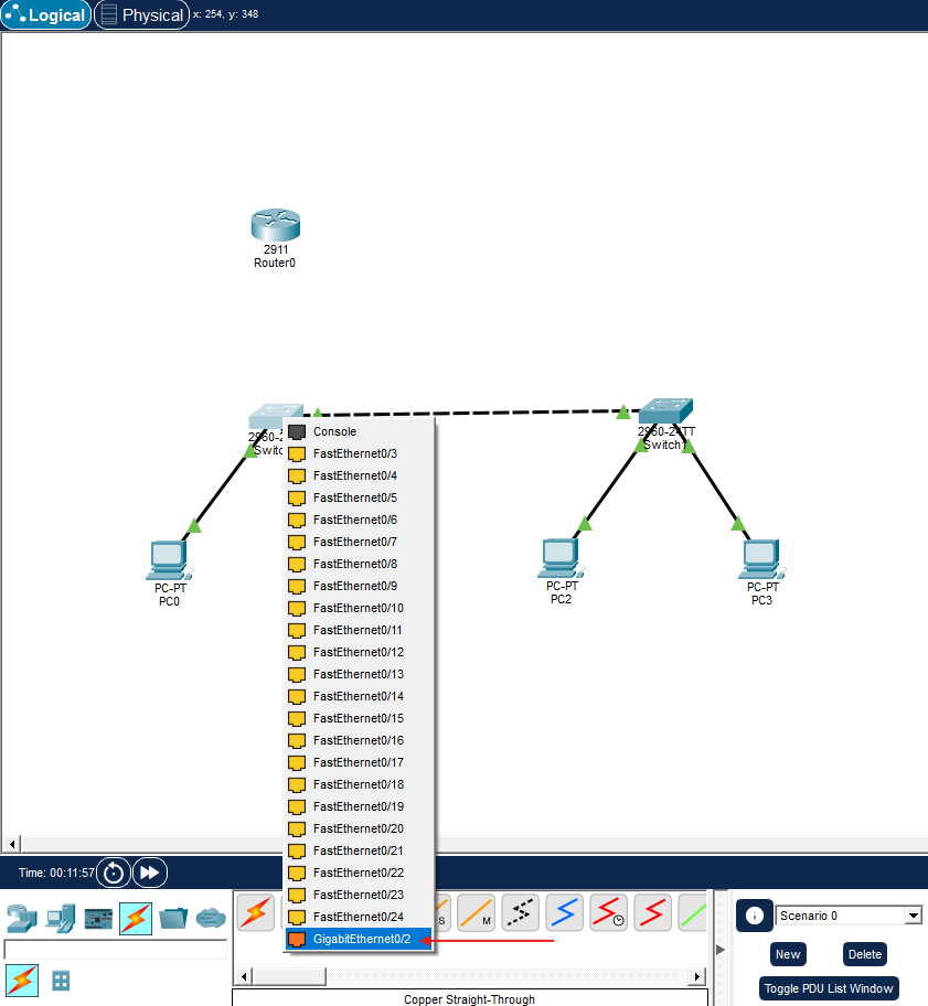
Select the Lightning Section to reach the cable types. Select the solid black cable, which is the Copper Straight-Through cable.
Click on the main switch, and select the empty GigabitEthernet 0/2 port.
Connect the other end to the Cisco 2911 Router and choose the GigabitEthernet 0/0 interface.


Configuring the Switch Link as a Trunk Port
Right now, the cable going to the router acts like a standard port. We need to tell the switch: ‘This cable will carry traffic for both VLAN 10 and VLAN 20.
To make this happen, follow the steps below:
Go to the CLI of the main switch connected to the router and press Enter.

Run these commands in order:
enable
This command allows us to enter the privileged mode to start managing the switch
configure terminal
This opens the global configuration mode so we can make changes to the switch settings
interface GigabitEthernet 0/2
This selects the specific high-speed port connected to our router for configuration.
WARNING: Whichever port you connected the cable to on the switch, you must type that port after the interface command. For example, if you connected it to fa0/24 instead of g0/2, you should change the command to interface fastEthernet 0/24.
switchport mode trunk
This changes the port’s mode to a trunk link, allowing it to carry traffic from multiple VLANs to the router
exit
This exits the interface settings and takes us back to the global configuration menu

Accessing and Activating the Router CLI
Click on the Router, and the system asks if you want to use the automatic setup wizard. Say No and press Enter because we’ll set everything manually:

Now, let’s activate the physical port on the router. Router ports are disabled (shutdown) by default, which is why the link lights are red. To wake up the port, use the following commands:
enable
configure terminal
interface GigabitEthernet 0/0
no shutdown
The moment you type the no shutdown command, you will see the light on the router's interface turn green in Packet Tracer.
exit

Subinterfaces and the Magic Touch
We have activated the physical interface, but left it without an IP address. That’s because we are going to split this single cable into two. You can think of it like partitioning a hard drive on a computer into C: and D: drives.
We’re still on the router's configuration panel.
To create the Subinterface for VLAN 10 (Accounting):
interface GigabitEthernet 0/0.10
When we add .10 to the end of the port name, the router automatically moves into the subinterface configuration mode: Router (config-subif)# :

encapsulation dot1Q 10
This critical command tells the router to accept and process traffic tagged with VLAN 10 using the industry-standard 802.1Q encapsulation protocol. By doing this, we bind our virtual subinterface directly to the specific VLAN we created on the switch
ip address 192.168.10.1 255.255.255.0
This command assigns the specific IP address 192.168.10.1 to the interface, which will act as the default gateway for all devices in this subnet. The subnet mask255.255.255.0 defines the network boundaries, allowing up to 254 usable IP addresses for the connected hosts.
exit

We configured the Default Gateway IP address, which serves as the exit point for VLAN 10 hosts to reach outside networks or the internet.
To create the Subinterface for VLAN 20 (IT):
interface GigabitEthernet 0/0.20
encapsulation dot1Q 20
ip address 192.168.20.1 255.255.255.0
exit

The router is now ready to listen to both VLANs and act as a bridge (routing) between them!
Configuring the “Default Gateway” on Computers
Now, we will access each PC in Packet Tracer individually to configure the router’s subinterface IP addresses as their default gateway.
For VLAN 10 (Accounting) PC:
Click on the first PC of VLAN 10, then select the IP Configuration panel:

Enter the VLAN 10 router IP (192.168.10.1) into the Default Gateway box:

Apply the same step to the other PC (192.168.10.11) of VLAN 10:

For VLAN 20 (IT) PC:
Click on the first PC of VLAN 20, then select the IP Configuration panel. Enter the VLAN 20 router IP (192.168.20.1) into the Default Gateway box:

Apply the same step to the other PC (192.168.20.11) of VLAN 20:

The Ultimate Test: Verifying Inter-VLAN Routing with Ping
Open the Command Prompt from a PC in VLAN 10 (Accounting):

Send a ping to a PC in VLAN 20 (IT):
ping 192.168.20.10

The first one or two ping packets might drop, showing a ‘Request Timed Out’ error. This is completely normal! In the background, the router runs ARP (Address Resolution Protocol) to learn the MAC addresses of the devices. The 3rd or 4th packet will definitely return successfully with a ‘Reply from…’ message. When you ping again, you will see a 100% success rate.
In short, we successfully divided one physical port into virtual parts to connect different VLANs. Now, your Router-on-a-Stick setup is ready, and your network can communicate smoothly and safely.
Informative, right? :) Let’s see each other in HomeLab #3; we’ve worked enough for today! You’ve crushed it! Time to rest! Byeee

메타데이터
- post_id
- f87cc4c33f6d
- slug
- connecting-isolated-networks-inter-vlan-routing-with-router-on-a-stick-homelab-2-f87cc4c33f6d
- url
- https://medium.com/@katedtcore/connecting-isolated-networks-inter-vlan-routing-with-router-on-a-stick-homelab-2-f87cc4c33f6d
- canonical_url
- https://medium.com/@katedtcore/connecting-isolated-networks-inter-vlan-routing-with-router-on-a-stick-homelab-2-f87cc4c33f6d
- author_url
- https://medium.com/@katedtcore
- status
- ok
- fetched_at
- 2026-06-21 22:26:41