What If Every Step Generated Power? Designing a Solar-Piezo Tile on Tinkercad
What if every step we took generated power? In cities filled with millions of footsteps every day, we walk over an enormous amount of…
What If Every Step Generated Power? Designing a Solar-Piezo Tile on Tinkercad

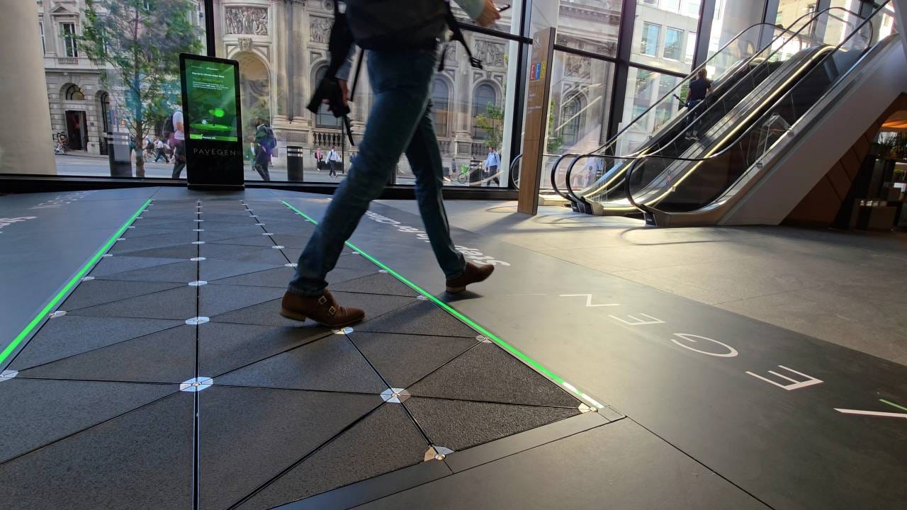
Figure 1.1 // Image on Euronews // Man stepping on solar panels outside
What if every step we took generated power? In cities filled with millions of footsteps every day, we walk over an enormous amount of wasted kinetic energy and sunlight. This question became the starting point of this project on Tinkercad, where I designed a solar-piezoelectric energy tile that captures both sunlight and footsteps. I built the full prototype in Tinkercad using real electrical components and a live circuit simulation of how it would look like in real life applications.
Beneath the Pavement: An Untouched Resource
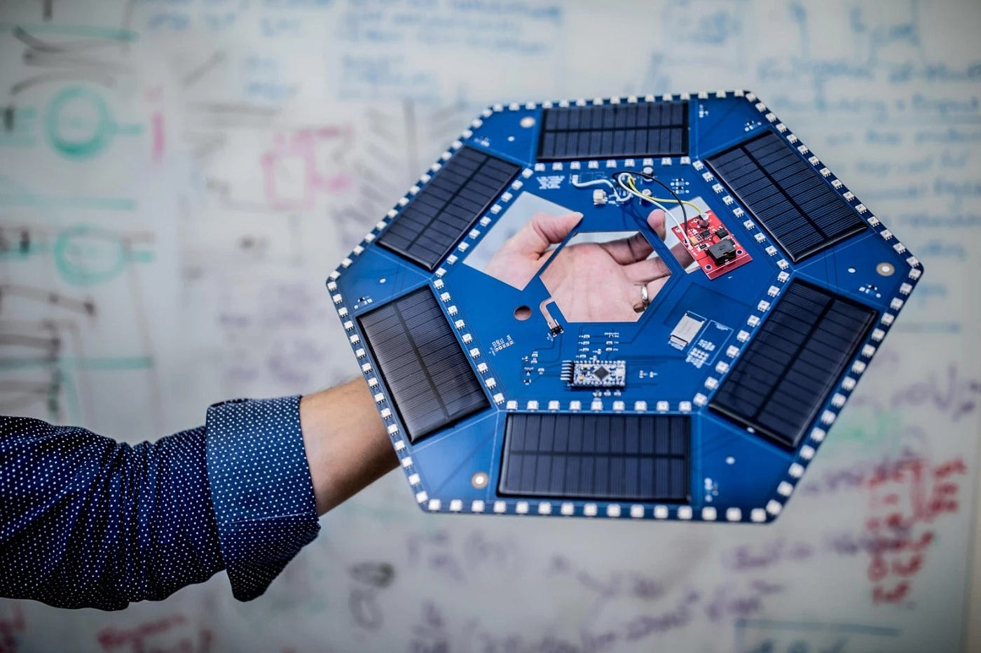
Figure 2.1 // Image by NASA on News Atlas // NASA’s Piezoelectric Tile
Modern cities rely heavily on large power grids that are often overstressed, expensive to maintain, and vulnerable to outages. Even small systems like street sensors, pathway lights, and public displays depend on this same centralized power source. At the same time, city surfaces such as pavement are unused opportunities for energy collection. Sidewalks receive constant sunlight during the day and experience nonstop foot traffic regardless of time, yet this energy has been relatively untouched. Gathering a small fraction of this potential energy can make a real difference especially regarding dependence. Solar-piezoelectric tiles can capture sunlight and kinetic energy, store it in super capacitors, and supply it to low-voltage electronics like LEDs that can signal information. These systems reduce our reliance on the main grid that make our cities more energy efficient and energy sustainable.
Visions of Sustainability: My Process in Designing a Hybrid Tile
Using a tool called Tinkercad, I designed an idea that I had integrating both solar cells and piezoelectric material into one tile that feeds into a super capacitor. The super capacitor acts like a temporary battery that can charge small voltage electronics such as sensors. In Tinkercad I used a LED to act like the electronic you would need electricity for. But how does that look like in perspective?
If you want a video demonstration of how I built it:
[embed]Video by Daniel Fung on Youtube // Steps on how to make Piezo-Solar Tile
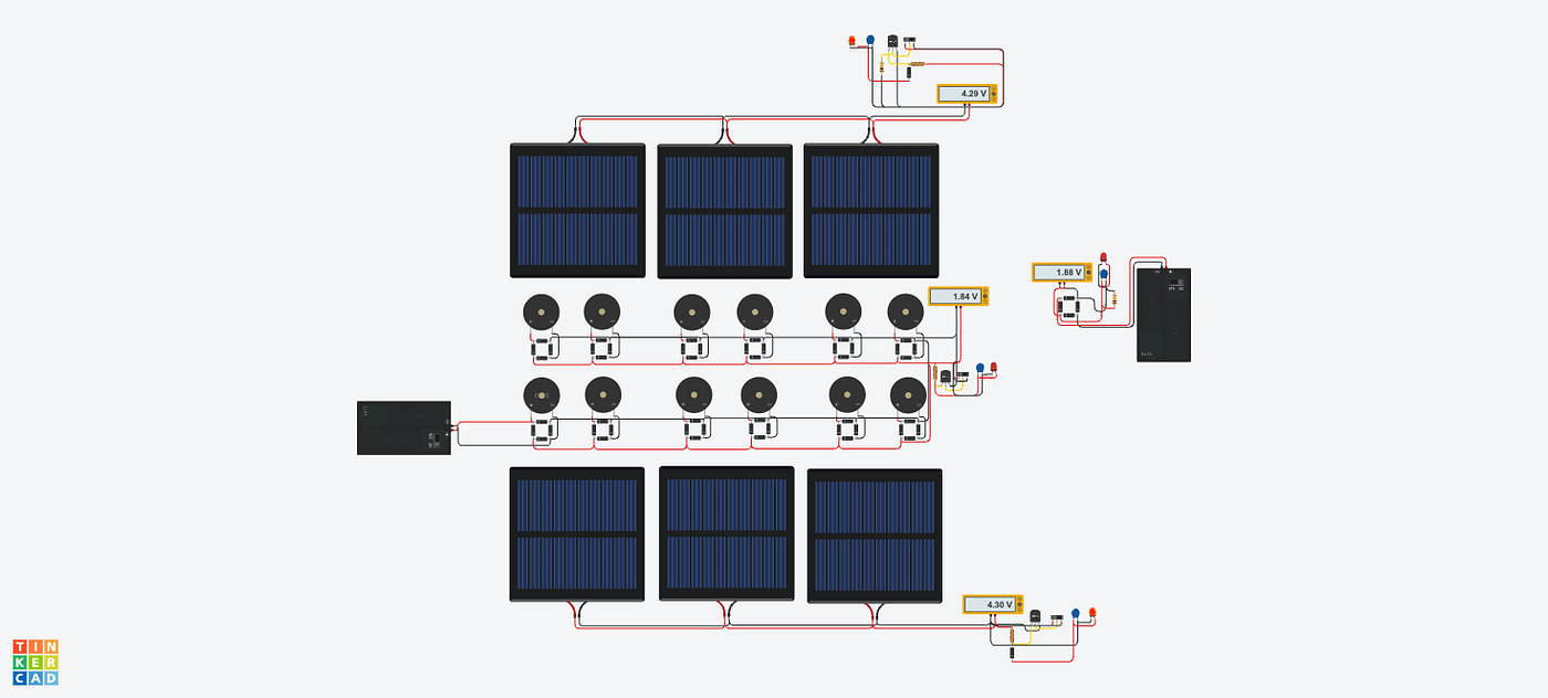
Figure 3.1 // Image by Daniel Fung on Tinkercad // Full overview of “30cmx30cm” Prototype
Looking at the full prototype it consists of: Solar cells connected in parallel and several piezos connected in parallel feeding into a super capacitor.
A solar cell generates DC electricity whenever it is exposed to light. While a piezoelectric disc produces AC electricity every time someone steps on the tile, through converting mechanical pressure into electrical energy. Let’s look closer into how the solar components are connected with each other.
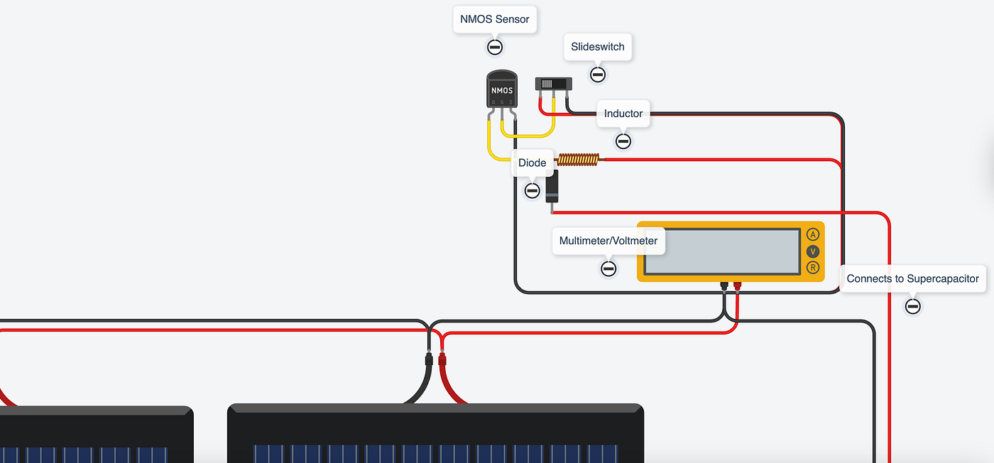
Figure 3.2 // Image by Daniel Fung on Tinkercad // Solar panels connection to supercapacitor
Solar panels create direct current that can be easily be stored in a super capacitor. However, with the piezoelectric-solar hybrid system we want, they must connect to the same super capacitor. Connecting it to the super capacitor has relatively simple steps, but the wiring is more challenging.
Step 1 → Solar Panels in Parallel → Voltmeter →
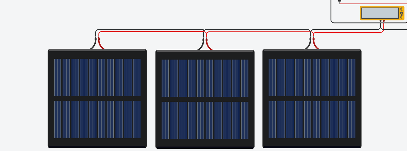
Figure 3.3 // Image by Daniel Fung on Tinkercad // Connection of solar panels to voltmeter
First, connect the negative and positive lines of the solar panels in parallel. Parallel connections have a shared path that all of the solar panels feed into. By connecting the panels in parallel we can have a more stable and shared voltage. As well as keeping the same voltage, it increases the current that feeds through the system which is what charges the super capacitors faster. Once in parallel, connect the negative and positive ends to a voltmeter that confirms whether the parallel connection is correct. If the meter reads what the output is for the solar panel then it is correct.
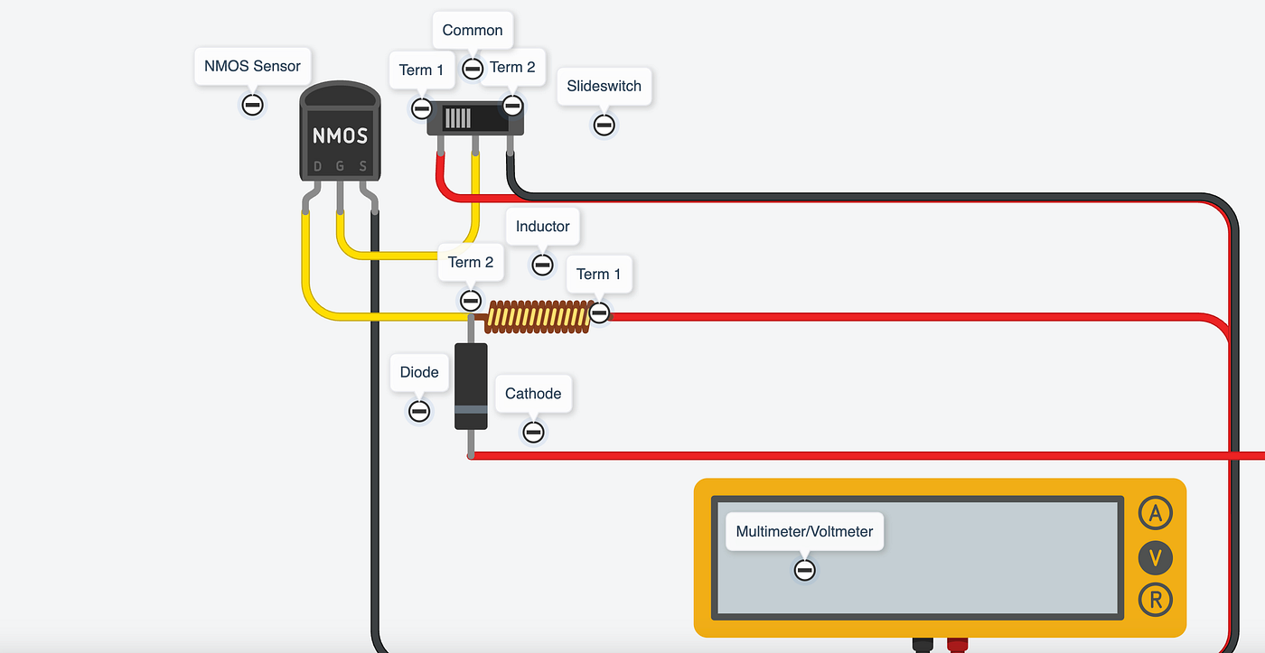
Figure 3.4 // Image by Daniel Fung on Tinkercad // Connection from voltmeter to NMOS, slide switch, inductor and diode
We now need a BQ25570 Nano Power Boost Converter that takes in small amounts of energy from the solar and piezo sources then boosts it to a higher voltage. The BQ25570 delivers a clean, stable output voltage so the voltage in the system stays consistent even when the input from the solar or piezo sources fluctuates while also preventing back flow into the solar panels. For the BQ25570 specifically, it can withstand voltages of both the solar panels and piezos. In Tinkercad there is not a electronic for the BQ25570, but we can replicate the same actions it does with the NMOS sensor, slide switch, inductor and diode.
Place down the NMOS, slide switch, inductor and diode and follow next steps to wire these components together.
“→” means wire connection
Step 2 → Voltmeter Positive (RED) → Inductor Terminal 1 + Slide switch Terminal 1
Step 3 → Voltmeter Negative (BLACK) → NMOS Source (S) + Slide switch Terminal 2
Step 4 → Now connecting the rest of NMOS’ pins (D) and (G): NMOS’ Drain (D) → Inductor’s Terminal 2 NMOS’ Gate (G) → Slide Switch’s Common
Step 5 → The Diode’s anode (not striped side) connects to the inductor’s terminal 2 while the cathode is connected to the positive side of the capacitor (Terminal 1 of Capacitor). Lastly connect the voltmeter’s negative side to the capacitor’s terminal 2. Following this wiring step by step will give the end result of the image.
Step 6 → Repeat same steps on other side of the tile for the other solar panels
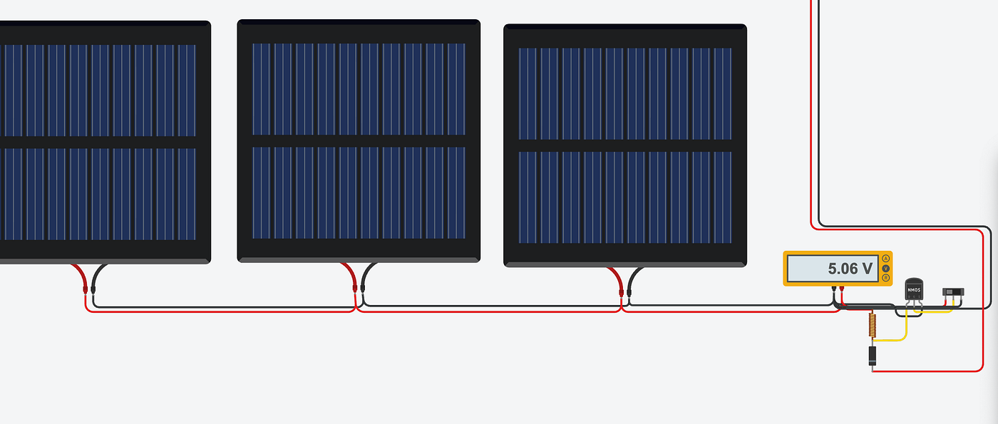
Figure 3.5 // Image by Daniel Fung // Overview of the bottom solar panels (“other solar panels”)
Now onto the piezoelectric component connections:
Components needed: Piezos, Diodes (Rectifier), voltmeter, NMOS, Slide switch, inductor, capacitor, LED
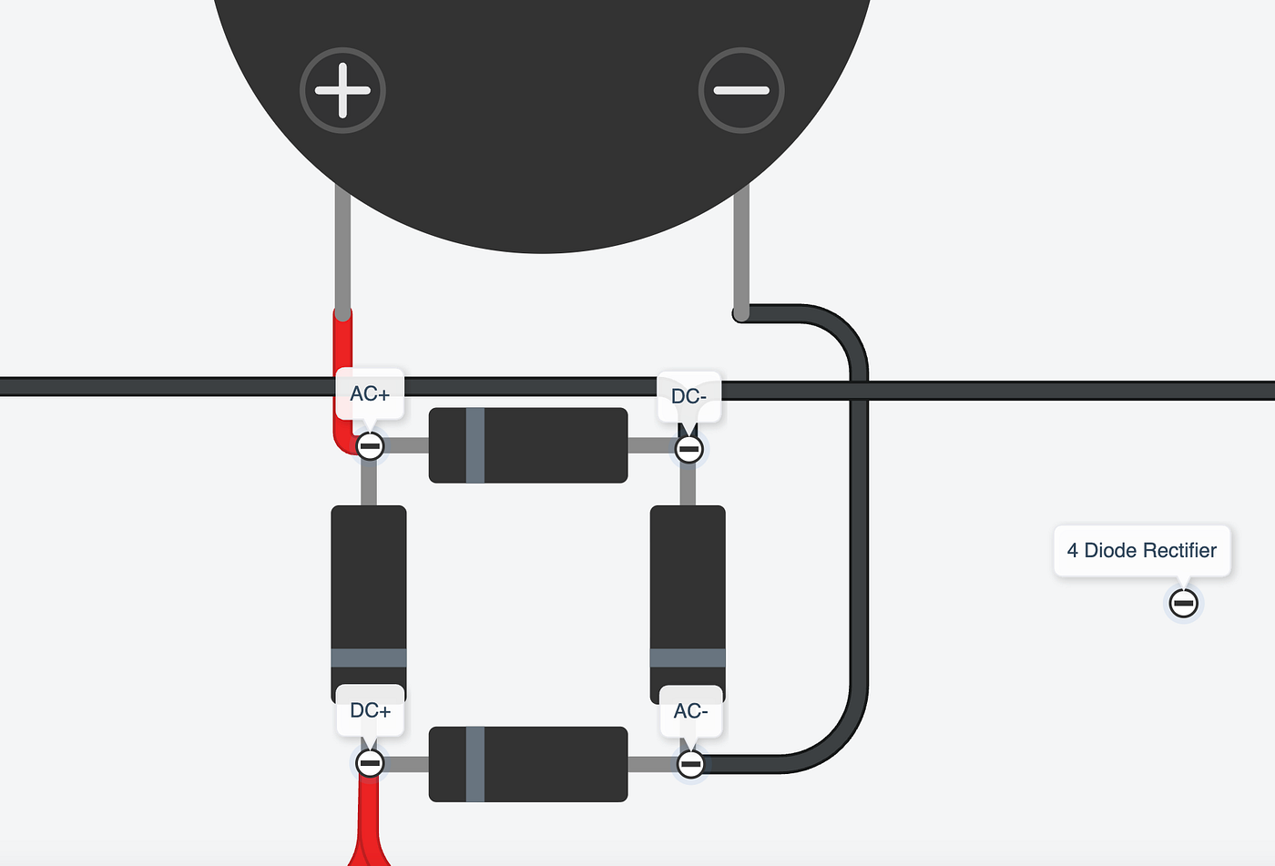
Figure 3.6 // Image by Daniel Fung on Tinkercad // Piezo connecting to 4 diode rectifier
Step 1 → The piezo discs generate alternating current (AC) when pressure is applied, but the electronic components require direct current (DC). To change this, the piezo leads are routed through a bridge rectifier (4 Diodes connected), which converts the AC into DC so it can be safely used. At the same time, the rectifier’s diodes prevent any back flow (alternate current goes back in forth in a circuit) of electricity, ensuring that energy stored in the capacitors does not flow back into the piezo discs. This allows the bursts of energy from the piezos to be reliably taken in and sent towards the next components.
To make the rectifier you need 4 diodes that are arranged as such:
- Mark your diodes: Diode 1 = (D1)…
- D1 Cathode to D2 Cathode (Striped ends) to make the DC+ output
- D3 Anode to D4 Anode (Not striped ends) to make the DC- Output
- Now connect D4’s Cathode to D1’s Anode
- D3’s Cathode to D2’s Anode
It should like this at the end.
Figure 3.7 // Image by Daniel Fung on Tinkercad // Zoomed in image of how the rectifier diodes are formatted
Consider the negative and positive lines from the piezo as “AC” and the output lines as “DC”. Connect the positive line from the piezo to AC+ on the rectifier (see image above) and the negative line to AC-
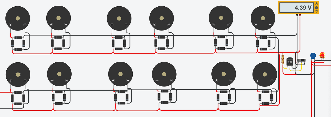
Figure 3.8 // Image by Daniel Fung on Tinkercad // Overview of how the DC+ and DC- should be connected in parallel
Step 2 → Each piezo has two leads, positive (RED) and negative (BLACK) and they need to be wired in a way that maximizes the tiny bursts of energy they produce.
To keep the voltage manageable and increase the current from each step, the piezos are connected in parallel, just like the solar panels. All the negative leads were tied into one shared line, and all the positive leads into another. This setup ensures that even if one disk receives more pressure than another, every piezo contributes to the overall output without interfering with the others.
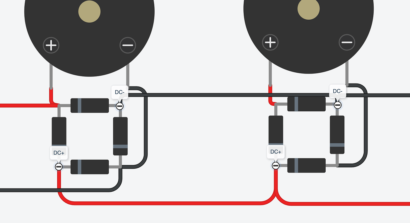
Image 3.9 // Image by Daniel Fung on Tinkercad // Parallel connections between DC- to DC- and DC+ to DC+
Connect the DC- of a piezo to another DC- and connect a DC+ to another DC+ until all piezos are connected in parallel. See image above for parallel connection.
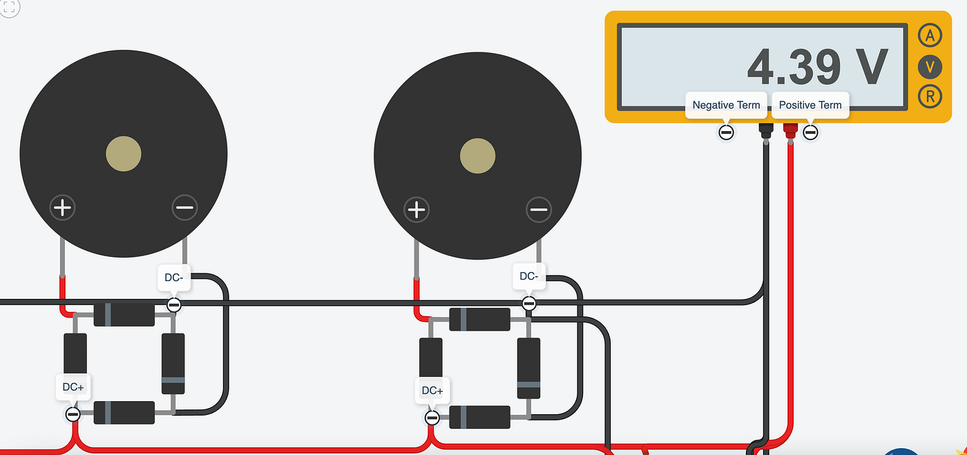
Figure 3.10 // Image by Daniel Fung on Tinkercad // Parallel DC- goes into voltmeter’s negative terminal; Parallel DC+ goes into voltmeter’s positive terminal
Then, connect the ends of the parallel (DC+) to the positive terminal of the voltmeter and the negative ends (DC-) to the negative terminal. The meter should read 0 volts since there is only a voltage once the piezo experiences mechanical force.
Now that the alternate current (AC) has been converted into direct current (DC), it can be connected to the NMOS, slide switch, inductor, diode and super capacitor. Exactly to the how I connected the solar panels to the super capacitor, follow these steps:
Step 3 → Voltmeter Positive (RED) → Inductor Terminal 1 + Slide switch Terminal 1
Step 4 → Voltmeter Negative (BLACK) → NMOS Source (S) + Slide switch Terminal 2
Step 5 → Now connecting the rest of NMOS’ pins (D) and (G): NMOS’ Drain (D) → Inductor’s Terminal 2 NMOS’ Gate (G) → Slide Switch’s Common
Step 6 → The Diode’s anode (not striped side) connects to the inductor’s terminal 2 while the cathode is connected to the positive side of the capacitor (Terminal 1 of Capacitor). Lastly connect the voltmeter’s negative to the capacitor’s terminal 2.
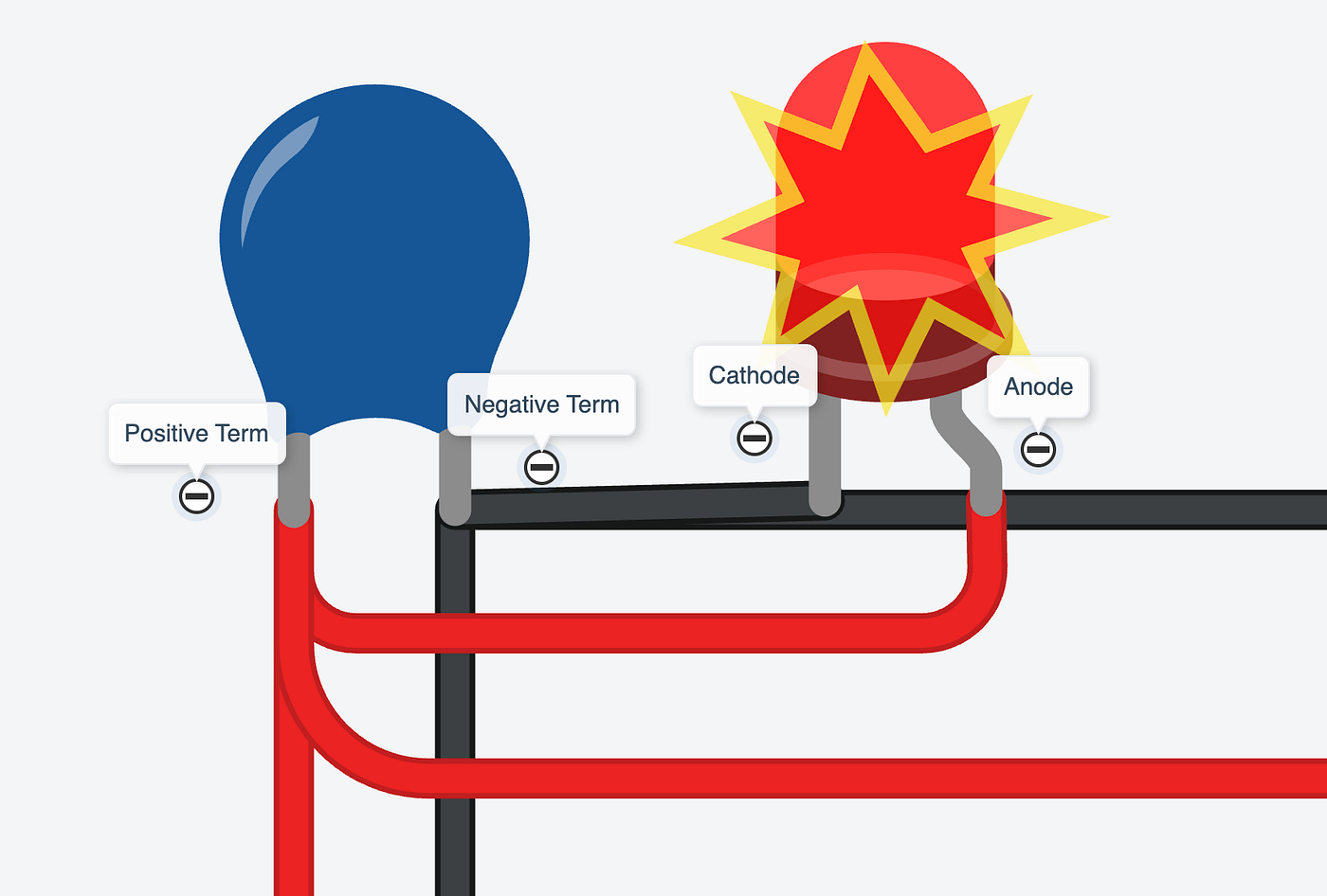
Figure 3.11 // Image by Daniel Fung // Capacitor to LED
Step 7 → Connect the negative terminal of the capacitor to the cathode of the LED then connect the positive terminal of the capacitor to the anode of the LED.
Figure 3.12 // Image by Daniel Fung on Tinkercad // Full wiring of solar panels and piezos to super capacitor
Step 8 → Start simulation. The LED should turn on and that will mean everything is connected correctly. In real life, the LED will not be on right away. This is because on Tinkercad the solar panels are programmed to a set output that doesn’t replicate the fluctuation you would see with real solar panels. Another thing is for the piezos on Tinkercad are noise-built rather than energy-primary. This means that when you click on it, it doesn’t send electrical pulses so to replicate this I added a 9V battery with a built in switch. By switching on and off, it replicates how piezos act and where the energy goes to.
Final Thoughts and Improvements:
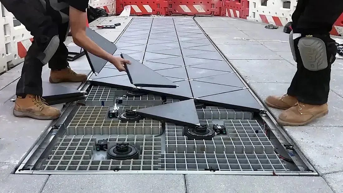
Figure 4.1 // Image by Shraddha Pandey on Parametric-Architecture // Piezoelectric tiles in Japan
Designing this solar-piezoelectric hybrid tile demonstrated how much unused energy exists in spaces that we use every day. From sidewalks, subway stations, and shopping centres, these places are full of potential energy.
Some improvements is cleaning up the wires so that the connections are clear. This is important because if this were to built in real life, the wiring would be all over the place making it confusing. Additionally, limiting the components to as little as possible is also a key improvement in the future as tiles components add up to the overall price and weight.
A system like mine may start small through powering small simple sensors, but if scaled to streets in urban cities it can reduce our reliance on the grid even if a small amount. With these tiles, the future of turning public spaces into active energy instead of passive surfaces is near.
Hey! My name is Daniel and I’m a 15 year old TKS innovator interested in Mechanical Engineering! I love building and designing different possible solutions to problems we have. In the future, I hope to become an entrepreneur and start a business from inventions I make in my engineering background. If you found this interesting and have questions, don’t hesitate to reach out to me at danielfung0529@gmail.com. Thank you for reading and hope you enjoyed it!
If you want to go through my design on Tinkercad:
Acknowledgements:
I want to thank Tinkercad for the resources it provides. It was super simple to use and the wire connections were easy as the ends were always labelled. Even though the wiring looks complicated, the labels helped me get familiar with the software and I ended up understanding why this component connected to another. Again, thank you.
Words Cited:
Tinkercad. “Learn How to Use Tinkercad.” Tinkercad, www.tinkercad.com/learn. Accessed 15 Nov. 2025.
Tinkercad. “Official Guide to Tinkercad Circuits.” Tinkercad, www.tinkercad.com/blog/official-guide-to-tinkercad-circuits. Accessed 15 Nov. 2025.
Bits4Bots, and Instructables. “Bits4Bots — Make a Bridge Rectifier from Diodes.” Instructables, Instructables, 26 Oct. 2023, www.instructables.com/Make-A-Bridge-Rectifier-From-Diodes/.
메타데이터
- post_id
- fa4f550d78b2
- slug
- what-if-every-step-generated-power-designing-a-solar-piezo-tile-on-tinkercad-fa4f550d78b2
- url
- https://medium.com/@daniel-fung/what-if-every-step-generated-power-designing-a-solar-piezo-tile-on-tinkercad-fa4f550d78b2
- canonical_url
- https://medium.com/@daniel-fung/what-if-every-step-generated-power-designing-a-solar-piezo-tile-on-tinkercad-fa4f550d78b2
- author_url
- https://medium.com/@daniel-fung
- status
- ok
- fetched_at
- 2026-06-28 10:39:35