What is the second OTA partition on the ESP32 useful for, other than for an online update?
For an online update on a processor from the ESP32 family, a second application partition is absolutely essential, as this is where the new…
What is the second OTA partition on the ESP32 useful for, other than for an online update?
For an online update on a processor from the ESP32 family, a second application partition is absolutely essential, as this is where the new code is stored during the download; subsequently, the ESP32 boots from this second partition. In this tutorial, I will show you the purpose of this second partition and how you can utilize it in your own programs — all you need is a little preparation and a few lines of code.
Topics of this tutorial
- ESP32 Default Configuration
- Brief Information on the Over-the-Air Update Process
- What else can the second program partition be used for?
- Solution for my Out Of Memory issue
- Simplified Test Environment
- Uploading the binaries
- Troubleshooting
- Using OTA Technology for the Nixie-Style Clock
- Summary
ESP32 Default Configuration
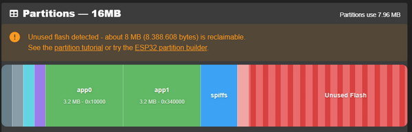
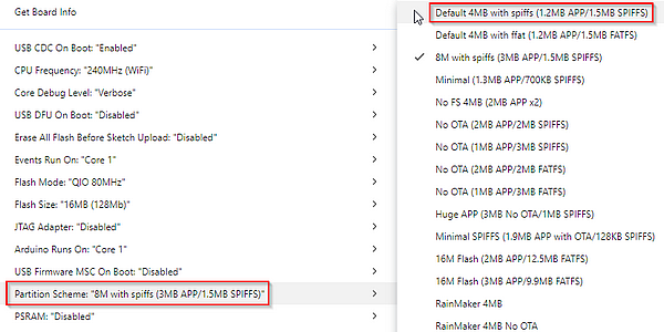
When you upload a program to the ESP32 processor, you will typically use the “Two Partitions” memory formatting, as this is the default setting. The allocation of the flash memory is controlled by the partition scheme, which can be changed within the “Tools” section of the Arduino IDE:
Brief Information on the Over-the-Air Update Process
An Over-the-Air (OTA) update on an ESP32 is the process of wirelessly uploading new firmware or code to the device, eliminating the need for a physical USB connection. This is especially useful for devices that are already installed in hard-to-reach places like ceilings or outdoor enclosures.
How It Works
- Dual-Partition System: The ESP32 uses a “safe update” mechanism where the flash memory is divided into at least two application slots (e.g.,
ota_0andota_1). - Background Download: While your current code is running, the new firmware is downloaded and written to the other (inactive) partition.
- Verification & Switching: Once the download is complete, the ESP32 verifies the new image. If valid, it updates a “data partition” to tell the bootloader to use the new slot on the next restart.
- Rollback Safety: If the new firmware fails to boot or has critical errors, the system can automatically roll back to the previous working version to prevent the device from becoming “bricked”.
What else can the second program partition be used for?
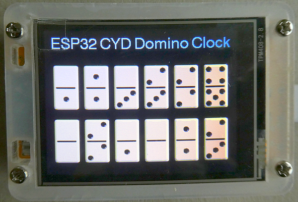
Let me give you a practical example of why I had to use the second program partition: as part of my tutorial “**How do I find the correct connection pins for an ESP32-S3 development board with an attached TFT display (ST7789)?**”, I demonstrated — among other things — a program that emulates a Nixie-style clock on the TFT display.
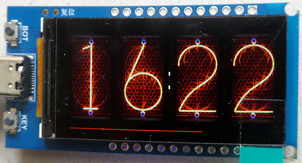
This clock connects to the local Wi-Fi network, then synchronizes with a Network Time Protocol (NTP) server and calculates the local time using a POSIX configuration string. As is the case in many other projects, the access credentials and the country-specific POSIX string are hardcoded into the program; consequently, any subsequent changes — such as updating the Wi-Fi credentials — necessitate reprogramming.
As a small added feature, I thought it would be cool to include a Bluetooth Low Energy (BLE) interface to transfer the Wi-Fi credentials and the POSIX string to the ESP32 using a smartphone. This allows the credentials to be easily changed later on — completely without the need for reprogramming. The transmitted data is permanently stored in Non-Volatile Storage (NVS), so that, in principle, I only need to perform this process once.
I tested the interface using a simple program that outputs all ESP32 data entirely to the Serial Monitor, and everything worked to my complete satisfaction. I copied the BLE code into a separate file and then, with just a few clicks, integrated it into the main code of the clock program.
Then came the great disillusionment: nothing worked anymore. There was no display on the screen, and the BLE connection was no longer active either. How is it possible that two separate programs function flawlessly beforehand, yet stop working after being merged? After an extended period of troubleshooting, I discovered the cause — and it is an “Out of memory error.”
Although my ESP32-S3 processor has 16 MB of flash memory available, there are nevertheless additional internal memory regions that do not scale up alongside a larger main memory (e.g., “DRAM” and “IRAM”). If an overflow occurs in these areas, a program may behave erratically — ranging from strange behavior to an uncontrolled crash.
It turned out that the “lightweight” BLE library is, in reality, a true memory hog — which, when used simultaneously with the TFT_eSPI graphics library involving numerous sprites, leads to the described memory bottleneck.
All attempts to avoid this bottleneck — for instance, by cleverly rearranging initializations or by conditionally deleting and recreating objects — failed; I found no way, given the architecture of my program, to utilize all three modules — the graphics library, Wi-Fi, and BLE — simultaneously.
Solution for my Out Of Memory issue
In the end, I found a small yet fascinating solution that fulfilled all my requirements: by utilizing the two completely separate program partitions (“OTA_0” and “OTA_1”), I can use both program components — specifically, the display of the current time and the configuration of the Wi-Fi interface — with my ESP32-S3.
The implementation is carried out using two independent sketches within the Arduino IDE: the clock component in OTA_0, and the BLE configuration component in OTA_1. The sole link connecting these two parts is their shared use of an additional Non-Volatile Storage partition, into which the OTA_1 program writes the new data, and from which OTA_0 reads these credentials to establish a connection with the Wi-Fi router and the NTP server.
Simplified Test Environment
To ensure we don’t lose sight of the essentials, I’ll start with a greatly simplified program — one that merely demonstrates how easily you can switch back and forth between two independent program sections. These two programs contain absolutely no code related to clocks or Bluetooth; however, they were immensely helpful to me — both for studying the fundamental workflow and for overcoming the minor hurdle of figuring out how to upload two separate programs to the ESP32.
It is crucial that both OTA programs utilize the same partition scheme. Furthermore, please note that the two programs are uploaded to the ESP32 processor in different ways:
- OTA_0: is compiled and uploaded to the ESP32 via the Arduino IDE.
- OTA_1: is merely compiled within the Arduino IDE to generate a binary file, which is subsequently uploaded to the second partition using an external service (“ESPConnect”).
Partition Scheme
Since our program is very small, we are using, for example, the default settings of the Arduino IDE (please note that default settings may vary depending on the specific ESP32 development board selected): “Default 4MB with spiffs (1.2MB APP/1.5MB SPIFFS)”.
Uploading the binaries
Uploading the OTA_0 Program
Uploading is performed just like with any other program, and the program is stored in the OTA_0 partition.
Compiling the OTA_1 Program
I had already mentioned that this program requires different handling for the upload. This is because Arduino always uploads a program to the OTA_0 partition.
In the Arduino IDE, please go to the “Sketch” menu and select “Export Compiled Binary”:
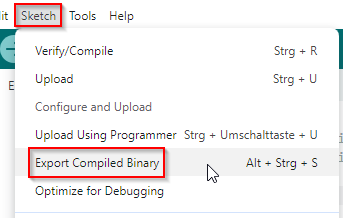
The sketch is now being compiled, and the “Output” window displays only this information:
Sketch uses 325,712 bytes (9%) of program storage space.
Maximum is 3,342,336 bytes.
Global variables use 22,096 bytes (6%) of dynamic memory,
leaving 305,584 bytes for local variables.
Maximum is 327,680 bytes.
Now, let’s use Windows Explorer or macOS Finder to look inside the Sketch folder — there, you will find a “build” subfolder, and within that, the folder “esp32.esp32.esp32s3” (this folder name may differ for you if you are using a different processor). Inside, there are several files, which may initially appear completely identical. Only one of these files is important to us: “Esp32_S3_Two_Partitions_Sketch_OTA_1.ino.bin”:
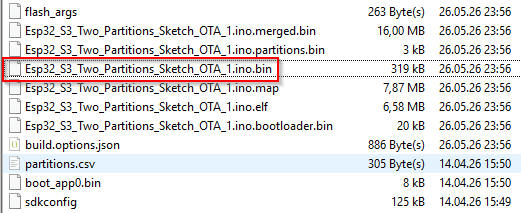
Using ESPConnect for uploading the sketch
In my tutorial “**Easily deploy and update your PlatformIO projects without an installed IDE,” I have already described [ESPConnect](https://thelastoutpostworkshop.github.io/ESPConnect/)**; therefore, you should read that article alongside this one.
After you have connected to the ESP32, select “Flash Tools” on the left side, and on the right side, scroll down slightly to “Flash Firmware”:
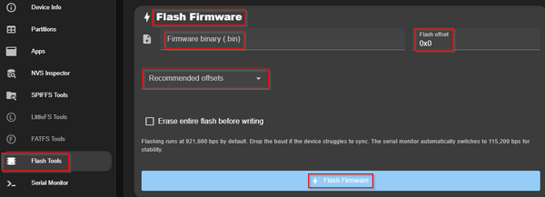
Click on “Firmware binary (.bin)” and then select the file “Esp32_S3_Two_Partitions_Sketch_OTA_1.ino.bin” from the subdirectory mentioned above. Now comes the most important step: open the dropdown menu under “Recommended offsets” and select “app1”:
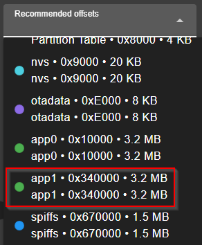
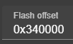
You will likely need to scroll down a bit; if “app1” does not appear there, you selected a partition scheme during the upload of the “OTA_0” program that is actually designed for only a single app (app0). The “Flash Offset” field is now also populated; the displayed value may vary depending on the specific memory configuration or data.
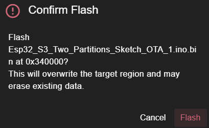
Finally, click “Flash Firmware,” and a final warning window will appear, as the existing content will subsequently be overwritten:
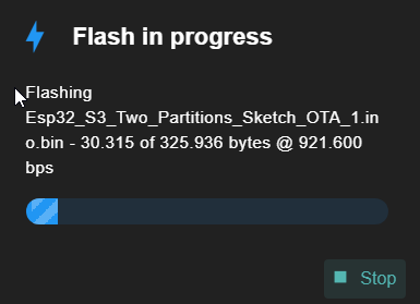
Two windows inform us about the progress and completion of the upload process:
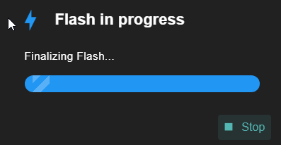
At this point, we have finished the upload, and the “OTA_0” program is ready for use. In the Serial Monitor, we see the following messages:
--- MODE: REGULAR (ota_0) ---
Please press the BOOT button to change to the EXTENDED mode.
Now, when we press the BOOT button, this happens (if nothing happens, please check the GPIO pin for the BOOT button on your board):
Change to ota_1 (Extended mode)...

<Restart of the ESP32-S3>

--- MODE: EXTENDED (ota_1) ---
Please press the BOOT button to change back to the REGULAR mode.
Upon clicking the BOOT button again, the ESP32-S3 switches back to Regular mode:
Change back to ota_0 (REGULAR mode)...
<Restart of the ESP32-S3>
--- MODE: REGULAR (ota_0) ---
Please press the BOOT button to change to the EXTENDED mode.
The program code for switching partitions is comparatively short:
in header:
#include "esp_ota_ops.h"

whereever you want to switch to OTA_1:
const esp_partition_t* target = esp_partition_find_first(
  ESP_PARTITION_TYPE_APP, ESP_PARTITION_SUBTYPE_APP_OTA_1, NULL);
if (target) {
  esp_ota_set_boot_partition(target);
  esp_restart();
} else {
  Serial.println("Error: ota_1 partition not found!");
}

For switching back to OTA_0 use:
const esp_partition_t* target = esp_partition_find_first(
  ESP_PARTITION_TYPE_APP, ESP_PARTITION_SUBTYPE_APP_OTA_0, NULL);
BTW: Of course, you can also upload subsequent updates for OTA_0 using the steps mentioned — just make sure to select the “app0” offset in ESPConnect!
Troubleshooting
Based on my experiments, I have identified three primary reasons for malfunctions:
-
Please take meticulous care to ensure that the settings within the “Tools” menu are exactly identical for both programs. Even the slightest discrepancy can result in entries being shifted, causing the uploaded code to be written to the wrong memory location. Particular caution is advised when loading a sketch created “some time ago.” Therefore, it would not hurt to embed the selected settings directly into the sketch file during the initial programming phase. For instance, it is very easy — and happens quite frequently — to inadvertently use an incorrect memory size and/or partition scheme, rendering the entire project unusable.
-
When uploading to ESPConnect, the browser remembers the last-used file location. If, for example, you are working with different versions stored in separate folders, it is very easy to accidentally upload the binary file from the previous version.
-
The order of uploads can determine success or failure: particularly for the first upload, it is crucial to upload OTA_0 via the Arduino IDE first, and only then upload OTA_1 via ESPConnect.
Using OTA Technology for the Nixie-Style Clock
In my article “**Upgrade your ESP32-S3 Nixie-style clock with a Web BLE interface**,” I show you how to integrate this technology into a project. In it, I utilize the two OTA partitions — one for the main program and the other for the WebBLE configuration program.
Summary
As you have seen, utilizing the two OTA partitions is very straightforward; the only discontinuity occurs during the upload process, as you have to manually initiate the upload for the second partition. This step might potentially be eliminated when switching from the Arduino IDE to PlatformIO, though I have not yet tested this myself.
Source code of the app
You find the complete code of the apps in my GitHub repository.
Happy coding !
메타데이터
- post_id
- fcb06672e2ec
- slug
- what-is-the-second-ota-partition-on-the-esp32-useful-for-other-than-for-an-online-update-fcb06672e2ec
- url
- https://medium.com/@androidcrypto/what-is-the-second-ota-partition-on-the-esp32-useful-for-other-than-for-an-online-update-fcb06672e2ec
- canonical_url
- https://medium.com/@androidcrypto/what-is-the-second-ota-partition-on-the-esp32-useful-for-other-than-for-an-online-update-fcb06672e2ec
- author_url
- https://medium.com/@androidcrypto
- status
- ok
- fetched_at
- 2026-06-12 18:14:10