Using DS1302 RTC module with Arduino
The Arduino can keep track of time very accurately using the millis() function, but only since the moment, it was powered up. If the…
Using DS1302 RTC module with Arduino
The Arduino can keep track of time very accurately using the millis() function, but only since the moment, it was powered up. If the Arduino is powered off or a reset is made, the Arduino timer starts with 0. This feature of Arduino is not very useful in case real-time is required in Arduino projects. We solve this problem using a Real-Time Clock (RTC) module.
What is an RTC module?
An RTC module keeps track of the real-time using an internal clock mechanism and a long-lasting battery. The module comes up with a 3V lithium-ion battery, a 32 kHz crystal and a DS1302 chip on a small board with five pins. The DS1302 chip is very power efficient and can run on the 3V lithium battery for up to 5 years.
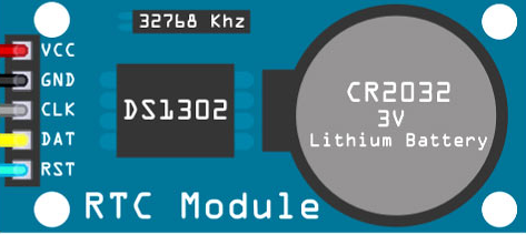
RTC Module
The supply voltage is 5V. RTC module uses the serial I2C communication protocol, which makes the interfacing of this module with the microcontroller very easy. Only two pins (CLK and DAT) are required for interfacing with Arduino other than VCC and GND. CLK and DAT pins are actually the required SCL and SDA pins for the I2C communication, while RST is the reset pin (optional).
Setting up the hardware
The Arduino has pins A4 and A5, especially for I2C communication. But with the help of software code, any pin can be used to serve the purpose. This is called a software I2C bus. For our goal, we would use the library “Rtc by Makuna” which is available in the Tools -> Manage Libraries… in the Arduino IDE. After the installation, the examples available along with the library can be used to know more about the functions and initialisation methods.

Library Manager Arduino
To work with the following code, connect DAT, CLK and RST pin of the RTC module with the digital pins 6, 7 and 8 in Arduino.
Writing the code
Now, our task would be to write the C code to set up the current date and time in the RTC module read from the module and write to the serial monitor each second.
[embed]Code for connection with RTC Module
The line ThreeWire DatClkRst (6,7,8); create a bundle of 3 wires which will be used to initialise the object Rtc from RtcDS1302 class using the command RtcDS1302<ThreeWire> Rtc(DatClkRst);
The function SetDateTime resets the date and time of the DS1302 chip. The date and time at the time of compilation of Arduino’s C code are stored in the RtcDateTime object “compiled”. The loop() method runs with a delay of 1 second. In each iteration, date and time are read from the RTC module and displayed on the serial monitor.
To understand the use of this RTC module, remove the line _ and flash the Arduino again with the updated code. Now, even if the power of Arduino is turned off or the RTC module is detached and attached back, the Arduino would be able to read and display the correct real-time.
메타데이터
- post_id
- fdfbcd7a8f13
- slug
- using-ds1302-rtc-module-with-arduino-fdfbcd7a8f13
- url
- https://medium.com/@rahuljain13101999/using-ds1302-rtc-module-with-arduino-fdfbcd7a8f13
- canonical_url
- https://medium.com/@rahuljain13101999/using-ds1302-rtc-module-with-arduino-fdfbcd7a8f13
- author_url
- https://medium.com/@rahuljain13101999
- status
- ok
- fetched_at
- 2026-07-29 06:21:49