Fascia and Soffit: How to Install an Aluminium Roofline System Correctly The Floating Fix, Thermal…
Most roofline problems that appear within the first five years of a new installation are not material failures. The aluminium did not fail…
Fascia and Soffit: How to Install an Aluminium Roofline System Correctly The Floating Fix, Thermal Movement, and the Sequence That Prevents Failure
Most roofline problems that appear within the first five years of a new installation are not material failures. The aluminium did not fail. The powder coat did not fail. The product was fine. What failed was the installation — specifically, one or more of the decisions about how the aluminium was fixed, how the joints were sealed, and whether thermal movement was properly accommodated throughout the system.
Aluminium roofline installation looks similar to uPVC installation on the surface. The same general sequence applies, the same types of components are involved, and the same tools are used for the most part. But aluminium has a different expansion coefficient from uPVC, it reacts galvanically with non-stainless fixings, it requires a specific sealant type that stays elastic permanently, and its cut edges oxidise if left unsealed. These differences are not complicated, but they require specific techniques that a contractor who has only ever installed uPVC may not automatically apply to their first aluminium job.
This guide covers the complete installation sequence for an aluminium fascia and soffit system, with specific focus on the technical decisions that distinguish a correctly installed aluminium roofline from one that develops problems. It is written for anyone installing aluminium roofline themselves, and for anyone commissioning the work who wants to understand what correct installation looks like so they can recognise whether it is being done properly.
Why Aluminium Roofline Installation Is Different From uPVC
Understanding the differences between aluminium and uPVC installation is not about making the job harder. It is about understanding the physical properties of the material and applying installation techniques that work with those properties rather than against them.
Thermal Expansion: The Governing Constraint
Aluminium expands and contracts with temperature changes. A standard 3-metre aluminium fascia section sitting in summer sun on a south-facing elevation can be up to 3mm longer than the same section on a cold winter morning. This does not sound like much, but multiplied across a long run of multiple sections, and concentrated at the joints between those sections, the cumulative movement is significant. Joints that have no provision for this movement sections simply butted together or fixed with no allowance for expansion will either buckle when the temperature rises or open when it falls.
uPVC expands more than aluminium under the same temperature change, which is why uPVC installation guides specify larger expansion gaps typically 5 to 10mm at joints. Aluminium’s lower expansion rate means smaller gaps 3 to 4mm at every union but the gaps are still essential. A common installation error made by contractors transitioning from uPVC to aluminium is applying uPVC expansion gaps to aluminium, which leaves the joints slightly looser than necessary without being a failure. A more serious error is applying no expansion gap at all because the aluminium looks tighter and more solid than uPVC and the temptation is to make it look finished rather than allowing for the gap.
The Floating Fix Principle
The floating fix is the installation technique that accommodates thermal movement in aluminium fascia panels. Rather than fixing the fascia rigidly through standard holes at every fixing point which would prevent any longitudinal movement and stress the panel as it tries to expand the fascia is fixed through slotted holes or oversized round holes that allow the panel to move slightly in the direction of expansion without stressing the fixing or the panel face.
The standard approach for aluminium fascia is to drill an 8mm hole for a 5mm stainless screw at each fixing position, or to use a factory-slotted hole where the slot runs horizontally along the length of the panel. The screw is not fully driven home it is tightened until firm but not crushing the fascia face, leaving the panel free to move longitudinally by a few millimetres as temperature changes. One fixing per section is made as a dead fix in the centre of the section to prevent the panel from translating along the run entirely. All other fixings are floating.
Galvanic Corrosion With Non-Stainless Fixings
Aluminium is an active metal in electrochemical terms. When aluminium is in direct contact with a dissimilar metal particularly carbon steel or galvanised steel in the presence of moisture, a galvanic reaction occurs. The aluminium acts as the sacrificial anode and corrodes at the point of contact. On a roofline installation this produces characteristic brown-black staining around each fixing point, progressive corrosion of the aluminium at the screw entry hole, and eventual failure of the fixing as the material around it is eroded.
The solution is simple and absolute: all fixings on an aluminium roofline installation must be stainless steel. A2 or A4 grade stainless steel screws are electrochemically compatible with aluminium and do not cause galvanic corrosion. There are no exceptions to this rule. A contractor who uses standard zinc-plated screws to fix aluminium fascia boards has made an installation error that will become visible within three to five years.
Cut Edge Oxidation
Unlike uPVC, which is coloured through the full thickness of the material, aluminium is coated on its surface. The powder coat covers the aluminium face, edges, and back, but the process of cutting a panel leaves a raw aluminium edge where the metal is exposed. This exposed aluminium oxidises in outdoor conditions, producing a white powdery bloom that spreads back from the cut edge and compromises the appearance of the installation in the vicinity of every cut.
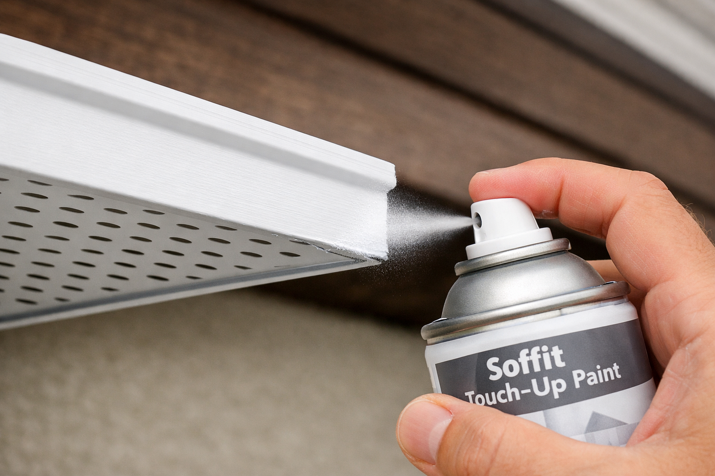
Sealing cut edges is not optional on aluminium roofline. Every cut must be deburred with a fine file or deburring tool, then coated with a touch-up aerosol in the matching RAL colour to seal the raw metal surface. The touch-up paint is not just cosmetic — it is protecting the aluminium from the oxidation process that would otherwise progress along the cut face. Most reputable aluminium roofline suppliers include a touch-up aerosol with the product.
Aluminium vs uPVC Installation: Key Technical Differences at a Glance
The table below summarises the most important technical differences that affect how an aluminium roofline system should be installed compared with a uPVC system:
Installation aspect
Aluminium
uPVC
Fixing method for fascia
Slotted or oversized holes (8mm for 5mm screw) floating fix allows thermal movement
Direct screw through standard holes; plastic clips on some systems
Expansion gap at joints
3–4mm at every union and joint trim
5–10mm at every union; larger movement range
Joint sealant type
Low-modulus silicone only stays elastic permanently
Low-modulus silicone or proprietary EPDM gasket systems
Cut edge treatment
Mandatory deburr and apply touch-up aerosol to every cut
No treatment needed material is coloured throughout
Saw blade requirement
Non-ferrous blade only fine tooth, TCT
Standard fine-tooth saw; manual hacksaw acceptable
Staggering of joints
Fascia joints staggered from soffit joints strongly recommended
Same principle applies but less critical plastic joints more forgiving
Corner treatment
Factory corner pieces or mitre with sealant both acceptable
Clip-on corner pieces mitres more prone to gap opening over time
Preparation: What Has to Be Right Before Any Board Goes Up
Rafter End Inspection
With the old boards removed, inspect every rafter end individually. Press a screwdriver tip firmly into each rafter end face sound timber resists, compromised timber does not. Any rafter that does not offer firm resistance throughout its end face is moisture-damaged and needs to be cut back to sound wood, treated with wood preservative, and either spliced with fresh treated timber or packed out to the correct fascia line.
For aluminium specifically, the rafter end condition is more consequential than for uPVC because the aluminium fascia will outlast any rafter repair work done today if the repair is inadequate. A splice repair that begins to soften again in 15 years will be holding the gutter brackets in the same aluminium fascia that was fitted today. Getting the rafter repair right the first time using structural-grade treated timber and fixing it correctly protects the investment in the aluminium system above it.
Checking the Rafter Line
Run a string line along the rafter ends of each elevation to confirm they are in a consistent plane. Any rafter end that projects beyond the line or sits behind it will produce a fascia that is not flat along its run. On a uPVC fascia, a slight deviation in the rafter line produces a wavy front face that is visible from the ground but has little structural consequence. On an aluminium fascia, the panel is rigid enough that a rafter end projecting beyond the line will actually put a stress-bend into the panel, which affects both appearance and the panel’s ability to accommodate thermal movement correctly at its fixings.
Pack or trim individual rafter ends as needed to bring them into a consistent line before any boards are fitted. This is a carpentry step that requires a spirit level or a taut string line and should not be rushed.
Confirming Soffit Depth and Ordering Correctly
Measure the eave depth the distance from the wall face to the front of the rafter end at several points along each elevation. This measurement determines the soffit board width to order. For aluminium soffits, the board can be fabricated to the exact measured width, which eliminates on-site trimming and produces a precise fit. Measure at five or six points along each run because eave depths vary more than expected on older properties. Use the widest dimension for the order on each elevation to ensure full coverage. Online Metal Store Ltd fabricate aluminium soffit boards to any width for exactly this reason.
The Installation Sequence: Soffit First, Then Fascia
The sequence is not negotiable on an aluminium roofline system. Soffit is installed first, fascia second. The rear of the fascia profile incorporates a return lip or channel that captures the front edge of the soffit panel. If the fascia is installed first, the soffit cannot be correctly engaged with this return — the front edge of the soffit ends up resting against the face of the already-fitted fascia rather than tucking behind its return leg.
Stage One: Fix the Wall Receiver
The wall receiver a J-channel or F-channel aluminium section is fixed to the wall face at the back of the eave before any soffit panels are installed. This channel receives the inner edge of the soffit board. It must be level, because the soffit panel will follow the receiver line and any deviation from level will be visible along the full soffit run from below.
Fix the receiver to masonry using stainless steel screws and appropriate wall plugs at 400mm centres. On older properties where the masonry at the eave line has softer joints, longer screws with larger plugs into the brick rather than the mortar may be needed to achieve a secure fix. Leave 2 to 3mm gaps between adjacent receiver sections for thermal expansion of the receiver itself. Fix receiver sections together with the internal joiner provided rather than butting them tight.
Stage Two: Install the Soffit Panels
Slide each soffit section into the wall receiver at the back and work toward the front edge of the eave. The front edge of the soffit will ultimately be captured by the return leg of the fascia, so at this stage it sits approximately at the rafter end position. Fix the soffit to the soffit bearer or directly to the underside of the rafter ends at intermediate points using stainless steel pins or screws at the centres specified for the specific soffit width.
At joints between adjacent soffit sections, use an internal joiner trim and leave a 4mm expansion gap between section ends. Apply a bead of low-modulus silicone to the exposed face of the joiner before the second soffit section is pressed home. The silicone seals the joint while remaining elastic enough to accommodate movement.
Stage Three: Fit Corner Pieces and Soffit Stop Ends
At external corners where the soffit run turns a projecting corner of the building fit the factory external corner piece before the straight runs reach the corner. The corner piece engages the receiver on both arms of the corner and the straight soffit sections butt to it with expansion gaps and sealant. At internal re-entrant corners, use the internal corner piece on the same principle.
Internal corner pieces are frequently skipped on site in favour of site-cut mitres when the correct factory corner piece is not available. A mitre at an internal corner of an aluminium soffit is a poor substitute the mitre is not structurally supported, the gap that opens as the panels move thermally creates a pest access point, and the appearance is inferior. Order the correct corner pieces with the main material order.
Stage Four: Install the Fascia Panels
With all soffit panels in place, the fascia installation can begin. Each fascia section is fixed directly to the rafter ends using the floating fix method slotted or oversized holes with stainless steel screws, one dead fix at the centre of the panel and all other fixings floating in the slots.
The return leg of the fascia profile engages the front edge of the soffit panel as the fascia is pushed up and back against the rafter ends. Confirm this engagement before fixing a soffit front edge that is not captured by the fascia return is not weather-tight and will be visible as a gap when the fascia is in place. The gutter will subsequently be fixed to the front face of the fascia, hiding the lower portion of the fascia face from view.
Fixing Spacing for Aluminium Fascia
Fixings for aluminium fascia should be at maximum 600mm centres, with an additional fixing within 150mm of each end of every section. The fixing at the centre of the panel is the dead fix. All others are in slotted or oversized holes. Do not fix into or through the union pieces at the joints the union must float freely to allow the thermal expansion gap to function.
Stage Five: Apply Sealant at Unions and Corners
Unions between fascia sections are sealed with low-modulus silicone applied to both faces of the union piece before each section is pushed home. The union sits behind the fascia face and is held in place by the pressure of the two adjoining sections on either side it is not fixed directly to the rafter or fascia backing. The 3 to 4mm expansion gap at each union is filled with sealant on the visible face of the joint after installation, tooled smooth, and the gap allows the sealant to flex with movement rather than being crushed by the panel ends.
At corner pieces external and internal apply sealant to the rear faces of the corner trim before pressing it to the fascia face at the corner position. Hold with low-tack masking tape until the sealant skins and the tape can be removed without disturbing the trim position. Clean any sealant smeared on the powder-coat face immediately with a damp cloth.
Stage Six: Seal All Cut Edges and Touch Up
Once all panels are in place, go back along every elevation and apply touch-up aerosol to every cut edge both the cut ends of panels visible at stop-end positions and any cuts made for ventilation disc holes, corner angles, or length adjustments. This step is often done as the job progresses, which is more efficient, but a final check at the end of the installation confirms nothing has been missed.
Stage Seven: Fix the Guttering
Guttering is the last component to go on. Gutter brackets are fixed through the fascia face into the rafter ends behind it, not into the soffit or into any other element. The bracket fixings need to reach into sound structural timber with at least 30mm of engagement. On a 2mm aluminium fascia board with a 50mm rafter end depth, a 75mm stainless screw through the fascia into the rafter end provides the required structural engagement.
The Joint Staggering Principle: Why It Matters and How to Apply It
A joint in any board is a point of reduced stiffness and potential moisture ingress. Where a soffit joint and a fascia joint coincide at the same position along the run both boards jointed at the same rafter bay there are two adjacent joints in the system at the same location. This concentration of joints at one point creates a compound weakness and a higher-risk area for moisture tracking at the eave.
The principle of staggering joints between the soffit and fascia means planning section lengths so that fascia panel joints fall roughly midway between soffit panel joints. If the soffit is jointed at rafter bay four, the fascia should be jointed at rafter bay six or seven, not at rafter bay four. On a 9-metre run this typically means ordering the soffit and fascia in slightly different section lengths for example, 4.5 metre and 4.5 metre for the soffit, and 3 metre and 6 metre for the fascia, or similar combinations that produce offset joint positions.
This is a planning step that needs to be done before cutting begins. Once the first section is cut and fixed, all subsequent joints in that run are determined by the initial cut. Working out the staggering in advance and marking the cut positions before picking up the saw is a ten-minute planning task that requires no additional material and produces a structurally superior installation.
Corners, Valleys, and Complex Roofline Geometry
External Corners
An external corner is where the fascia and soffit turn a projecting corner of the building the most common example is a hipped roof return or a bay window. Factory-made external corner pieces for aluminium roofline are the correct solution. They are formed to the exact profile of the fascia and soffit section, incorporate the correct return angle, and include internal sealant channels that make the corner weathertight.
Site-cut mitre joints at external corners cutting both fascia ends at 45 degrees and butting them at the corner are an inferior alternative that should only be used where a factory corner piece is genuinely not available. A properly mitered aluminium external corner requires careful cutting, deburring, touch-up on all cut faces, and very precise sealant application to produce a result that matches the quality of a factory corner piece. The thermal movement at a site-cut mitre is also more likely to produce a visible gap over time than a properly designed factory corner piece.
Internal Corners (Re-entrant Angles)
An internal corner where the fascia and soffit run meets a re-entrant angle of the building, as in an L-shaped plan property requires an internal corner piece. The principle is the same as for external corners: factory corner piece, sealant, hold with low-tack tape until set.
On properties with complex plan shapes U-shapes, T-shapes, or multiple re-entrant angles the corner piece count can be significant. Counting corners and ordering the correct quantity of internal and external corner pieces before the job starts is part of the pre-installation material check. Running out of corner pieces mid-installation and substituting a site-cut mitre at a difficult corner is the kind of shortcut that the homeowner will be looking at from the garden for the next 40 years.
The Gable End Box
Where the fascia and soffit turn from the eave run around the gable end of the building, a box end is formed. The box end is a triangular piece of fascia material that closes the open end of the soffit run at the gable. It requires careful measurement and accurate cutting because the box end face is visible and angled, and any inaccuracy in the cut angle is immediately apparent from the ground.
On aluminium, the box end cut faces must be treated with touch-up aerosol like all other cuts. The box end piece is fixed through its upper edge to the rafter timber at the gable end and sealed at its perimeter with low-modulus silicone. A poorly fitted box end on an aluminium roofline is one of the most visible quality indicators of the installation.
Flat Roof Extensions
On a flat roof extension, the fascia runs around the perimeter of the deck rather than following a pitched rafter line. The fascia is typically fixed to the deck edge joist or the timber fascia backer rather than to rafter ends. The soffit, if present, fills the gap between the external wall and the fascia face at the perimeter edge.
Flat roof aluminium fascia profiles are often deeper than pitched roof equivalents because they also need to cover the depth of the deck build-up below the waterproofing membrane. The floating fix principle applies equally on flat roof fascia the panel must be free to expand and contract along its length regardless of the structural element it is fixed to.
Integrating Ventilation Into the Aluminium Soffit System
On cold roof constructions where the roof void requires ventilation at eave level, the soffit must provide the equivalent ventilation area specified in Approved Document F. The aluminium soffit system can accommodate this in several ways.
Vented Soffit Panels
A vented aluminium soffit has perforations distributed across the face that provide the required equivalent area. When specifying a vented panel, confirm the published equivalent area for the specific panel width and perforation pattern and check it against the Approved Document F requirement for the roof construction. The required equivalent area for most cold pitched roof domestic applications is a continuous 10mm gap at both eave runs.
Disc Vents in Solid Panels
Where a solid panel is aesthetically preferred, circular disc vents are installed after the soffit panels are in place by drilling 70mm holes at the calculated centres along the soffit run. The disc vent is pressed into the drilled hole and its louvred face allows air to enter the roof void while preventing insect access. Ensure each drilled hole edge is sealed with touch-up aerosol before the disc vent is fitted.
Over-Fascia Ventilators
On some installations, particularly where the soffit panel width is minimal or where a solid soffit is fitted for other reasons, ventilation is provided by an over-fascia ventilator a profiled strip fitted between the top of the fascia and the underside of the roof covering that allows air to pass into the roof void without going through the soffit face. This is an equally valid solution and is preferred by some installers on properties where the soffit ventilation path to the roof void is restricted by insulation at the eave.
For specification guidance on matching ventilation provision to the specific roof construction, the fascia and soffit range with full technical specification is available from Online Metal Store Ltd, and their team can advise on the correct panel type and disc vent centres for particular roof constructions.
The Eight Installation Mistakes That Cause Most Aluminium Roofline Failures
These are the errors that recur on poorly installed aluminium roofline systems, what each one causes, and how to prevent it:
Mistake
What happens
How to avoid it
Fixed holes instead of slotted
Fascia buckles visibly in summer; may crack or distort at fixing points
Pre-drill slotted holes or use 8mm holes for 5mm screws throughout
No expansion gap at unions
Union is crushed in expansion; gutter brackets attached to fascia are stressed
Mark 3–4mm gap before fitting each section into its union
Standard neutral-cure sealant used
Sealant cracks at expansion joints within 3–5 years; joints begin to drip
Low-modulus silicone only confirm product spec before purchasing
Cut edges left unsealed
White oxidation bloom appears at cut face within weeks outdoors
Deburr every cut and apply matching touch-up aerosol to seal the raw aluminium
Fascia joints aligned with soffit joints
Structural weakness at the joint position compound movement concentrates stress
Plan section lengths so fascia joints fall midway between soffit joints
Using standard galvanised screws
Galvanic corrosion stains the fascia face and progressively weakens the fixing
Stainless steel (A2 or A4) only no exceptions on aluminium
Fascia fixed before soffit
Soffit cannot be correctly positioned because front edge has already been closed by fascia
Always fit soffit first; fascia covers the front edge of the soffit on installation
The Single Biggest Error on First Aluminium Installations
The single most common error on a first aluminium installation by a contractor who has only previously worked with uPVC is applying rigid fixings screws through standard-sized holes fully tightened into the panel face without slotted holes or any provision for thermal movement. The result is not usually immediate. The fascia looks excellent when it is installed. In the first hot summer, the fascia sections expand along their length. With nowhere to go, each section bows outward between its fixings. The bow may be slight perhaps 5mm at the midpoint of a 3m section but it is visible under raking light and it is permanent: the fixing points have slightly distorted and the panel does not return fully flat when it cools.
This failure is completely preventable with pre-drilled slotted or oversized holes at every fixing point except the central dead fix. The technique takes perhaps five minutes longer per section than simply driving screws through the panel face, and its absence produces an installation that is visibly imperfect for the life of the system.
Inspecting the Completed Installation Before the Access Platform Is Removed
The final inspection before dismantling the scaffold tower is the most efficient point to identify and correct any issues. Once the platform is down, any correction requires resetting the access setup.
• Walk the full length of each fascia run and look along it from one end. A correctly installed aluminium fascia should be visually flat and straight. Any visible bow, ripple, or point where a panel steps forward or back of the general line indicates a fixing or substrate issue that needs to be addressed.
• Check every joint for the expansion gap. Press gently on the fascia face on either side of each union. Sections that resist all movement are fixed too rigidly. Sections that move more than 2 to 3mm suggest the gap is too large and the sealant may not be bridging it effectively.
• Check all corner pieces and stop ends for full contact with the fascia face. Any corner piece that has lifted slightly at an edge has not been held long enough for the sealant to set, or the sealant was applied too thinly.
• Inspect the soffit from below using a torch if necessary. Look for any panel that has dropped or is not sitting flat against its bearers. Look for any open gap between the soffit front edge and the fascia return that would allow weather or pest access.
• Pour a bucket of water along each fascia run and check the soffit below for any drips or weeping at joints. New sealant and correctly installed unions should produce no flow behind the fascia face at all.
Completing the Coordinated Roofline: Fascia and Soffit in the Full System
The fascia and soffit are the foundation of the aluminium roofline system, but the visual and performance quality of the installation depends on all the components being matched. A 2mm aluminium fascia in RAL 7016 anthracite grey with a 1.5mm aluminium soffit from a different supplier in a slightly different grey, with the guttering in a third shade ordered at a different time, is a combination that reads as uncoordinated from the street regardless of how well each individual component was installed.
The principle of ordering the complete aluminium roofline system fascia, soffit, guttering, downpipes, drip trim, coping, and all accessories from a single supplier in a single powder-coat batch in the same RAL colour is the only reliable way to guarantee colour consistency across all visible roofline components. Online Metal Store Ltd supply the complete aluminium roofline system fabricated to order in any RAL colour, with bespoke sizing for all components and specification support for projects where the eave geometry is non-standard.
The aluminium fascia guide on the Online Metal Store Ltd blog provides further detail on the full fascia system including profiles, sizing, and the technical case for aluminium over uPVC for UK residential and commercial properties.
Conclusion
Installing aluminium fascia and soffit correctly is not significantly more complex than installing uPVC, but it requires applying the right techniques at the specific points where aluminium behaves differently. The floating fix. Slotted holes throughout except the central dead fix. Low-modulus silicone at every union and corner joint. Stainless fixings exclusively. A 3 to 4mm expansion gap at every union. Touch-up on every cut edge. Soffit before fascia, always.
These are not complicated rules. They are the decisions that distinguish an installation that looks excellent and performs reliably for 40 years from one that buckles in its first summer, stains at its fixings within three winters, and joints that crack within five years. The aluminium is a premium material investment the installation technique is what determines whether the investment pays off.
Frequently Asked Questions About Aluminium Fascia and Soffit Installation
1. Why does my new aluminium fascia have a slight bow in the middle of each section?
A bow in the middle of an aluminium fascia panel almost always indicates that the fixings were driven through standard-sized holes rather than slotted or oversized holes, and there is insufficient room for the panel to expand longitudinally as temperature rises. When the fascia expands and cannot move at its fixing points, it bows outward between them. The fix requires removing the affected sections, pre-drilling slotted or oversized holes at all fixing positions except the central dead fix, and refitting with stainless screws not fully driven home. This is one of the most common errors on first aluminium installations and is entirely preventable with the correct fixing technique.
2. How much expansion gap should I leave at aluminium fascia unions?
The recommended expansion gap inside an aluminium fascia union connector is 3 to 4mm. This allows the panel to expand on a hot day without the section ends making contact inside the union and buckling the run. The gap is sealed on the visible face with low-modulus silicone after installation, which stays elastic permanently and accommodates the gap opening and closing over thermal cycles without cracking. Do not use standard neutral-cure silicone at this joint it will harden progressively and crack within a few years of thermal cycling.
3. Can a uPVC-experienced installer do an aluminium roofline installation correctly?
Yes, provided they understand the specific differences in technique and apply them consistently. The main adjustments required from uPVC practice are: pre-drilling slotted or oversized holes rather than straight through-fixing; using exclusively stainless steel fixings; applying low-modulus silicone specifically rather than any exterior sealant; sealing every cut edge with touch-up aerosol; and maintaining 3 to 4mm expansion gaps rather than the larger gaps used on uPVC. A contractor who approaches aluminium with an open acknowledgement that it has different requirements from uPVC and takes the time to understand those requirements before starting will produce a quality result. One who applies uPVC techniques to aluminium without adjustment will produce a system that looks acceptable initially but develops problems within a few years.
4. Why must the soffit be installed before the fascia on an aluminium system?
The aluminium fascia profile incorporates a return leg at its rear that captures and covers the front edge of the soffit panel. If the fascia is installed first, this return leg is already fixed in position and the soffit front edge cannot be inserted behind it. The soffit would end up resting against the face of the fascia rather than being captured behind its return, leaving a gap between the soffit edge and the fascia face that admits weather and pests. The sequence exists because of the geometry of the profiles soffit first is always correct, and the fascia always goes on last of the boarding elements before the guttering.
5. How do I seal cut ends of aluminium fascia and soffit panels?
After each cut, run a fine file or deburring tool along the cut edge to remove metal burrs produced by the saw. Then apply a matching touch-up aerosol supplied by the manufacturer in the same RAL colour as the panels to coat the raw aluminium surface with a protective layer. Hold the aerosol about 20cm from the cut face and apply two thin coats rather than one heavy coat to avoid runs. The touch-up paint seals the aluminium against oxidation, which would otherwise produce a white powdery bloom at the cut edge within weeks of outdoor exposure. This step takes about thirty seconds per cut and is non-negotiable on aluminium roofline.
메타데이터
- post_id
- ff0d21df03b2
- slug
- fascia-and-soffit-how-to-install-an-aluminium-roofline-system-correctly-the-floating-fix-thermal-ff0d21df03b2
- url
- https://medium.com/@onlinemetalstoreltduk/fascia-and-soffit-how-to-install-an-aluminium-roofline-system-correctly-the-floating-fix-thermal-ff0d21df03b2
- canonical_url
- https://medium.com/@onlinemetalstoreltduk/fascia-and-soffit-how-to-install-an-aluminium-roofline-system-correctly-the-floating-fix-thermal-ff0d21df03b2
- author_url
- https://medium.com/@onlinemetalstoreltduk
- status
- ok
- fetched_at
- 2026-06-09 15:37:30


