System Design Basics: Avoiding Single Points of Failure in Distributed Systems
What is a Single Point of Failure?
System Design Basics: Avoiding Single Points of Failure in Distributed Systems
What is a Single Point of Failure?
The Definition
In computing, a single point of failure (SPOF) is any component where if it crashes, the entire system goes down.
Classic Example:
[Multiple Servers] → [Single Database]If that one database crashes → Everything fails.
Single Points of Failure: A Universal Concept
This isn’t just a computer science problem — it’s everywhere in life:
Humanity’s SPOF: Earth
- If a massive asteroid destroys Earth
- Humanity is wiped out
- Earth = our single point of failure
In Storytelling
- That one character everyone loves
- Too important to kill off
- The story depends on them surviving
- Character = narrative single point of failure
The pattern is universal: One critical component that cannot fail without everything collapsing.
When Does This Come Up in Interviews?
System Design Interview Context
Single points of failure are an advanced topic that comes up after you’ve covered the basics:
Interview Flow:
- ✅ Define multiple services
- ✅ Explain how they interact
- ✅ Show they meet requirements
- 🎯 Then interviewer tests your architecture’s resiliency
What They’re Really Asking: “Can your system survive failures? Or will one crashed component bring everything down?”
The Core Problem
Why SPOFs Are Bad Architecture
The Pattern:
Service A ──┐
Service B ──┼──→ [Critical Component] ←── If this fails,
Service C ──┤                              everything fails
Service D ──┘
Characteristics:
- Multiple components depend on one point
- That point crashes → entire system crashes
- Architecture is not resilient
Solution #1: Add Redundant Nodes
The Basic Fix
Problem:
- Service 1 (Profile Server)
- Everyone connects to it
- It crashes → No profiles for anyone
Solution: Add a second Profile Server that does the same thing.
Two Implementation Approaches
Approach A: Hot Backup (Active Standby)
Primary Server (Active) ──→ Handles all traffic
Backup Server (Standby) ──→ Waits for failure
For Services: This isn’t very useful because:
- Backup server sits idle with no connections
- What data would it even contain?
- Wasteful resource usage
For Databases: This makes perfect sense:
- Primary Database receives all writes
- Backup continuously mirrors data
- If primary fails → backup takes over
- Data is preserved
Understanding Database Redundancy
The Master-Slave Setup
Configuration:
Master DB ──→ Receives all writes

     ↓ (continuous replication)

Slave DB  ──→ Exact copy of Master
How It Works:
- Every change in Master is mirrored to Slave
- Slave is a backup of the data
- If Master fails, Slave can become new Master
The Probability Advantage
Math Behind Resilience:
Single Database:
- Probability of failure = P
Master + Slave:
- For system to fail, both must fail
- Probability = P × P = P²
- Much, much smaller chance
Example:
- If P = 0.01 (1% failure rate)
- P² = 0.0001 (0.01% failure rate)
- 100x more reliable!
Building a Resilient Architecture: Step by Step
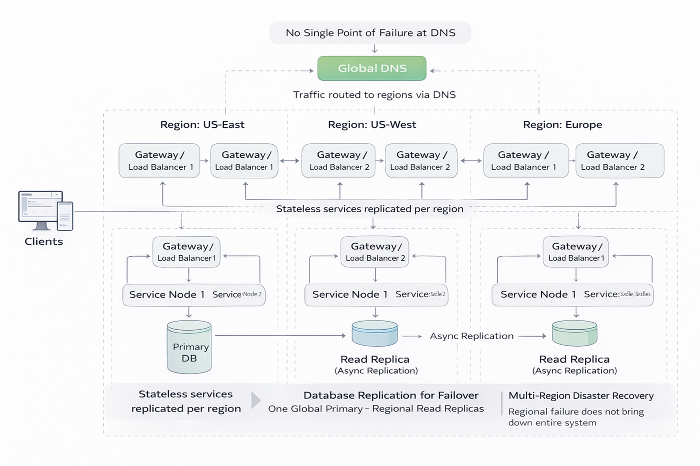
Starting Point: Basic System
[Client] → [Service] → [Database]Problem: Every component is a SPOF.
Step 1: Redundant Services
If one service node fails → entire service fails
Fix: Add another node
[Client] → [Service Node 1] → [Database]
           [Service Node 2]
Result: First layer of redundancy achieved.
Step 2: Database Replication
If database crashes → all data unavailable
Fix: Master-Slave architecture
[Services] → [Master DB]
                  ↓
             [Slave DB 1]
             [Slave DB 2] (read slaves)
Options:
- Read slaves: Handle read operations, reduce Master load
- Backup slaves: Pure replicas for failover
- Consistency choice: Perfect consistency might mean fewer read slaves
Result: Database layer is now resilient.
Step 3: Load Balancer (Creates New SPOF!)
Problem: With multiple service nodes, how do clients know where to send requests?
Solution: Add a Load Balancer
[Client] → [Load Balancer] → [Service Node 1]
                           → [Service Node 2]
But wait… The Load Balancer itself is now a SPOF!
Step 4: Multiple Load Balancers
Fix: Add redundant load balancers
[Client] → [Load Balancer 1] → [Services]
           [Load Balancer 2]
New Problem: Client doesn’t know which load balancer to connect to!
Step 5: DNS Resolution
Solution: Use DNS with multiple IP addresses
How DNS Works:
- Client wants to reach
facebook.com - DNS lookup returns multiple IP addresses
- Each IP points to a different load balancer
- Client can connect to any one of them
Example:
facebook.com resolves to:
→ 192.168.1.10 (Load Balancer 1)
→ 192.168.1.11 (Load Balancer 2)
→ 192.168.1.12 (Load Balancer 3)
Note: These are actually gateways with load balancing mechanisms, not just simple load balancers.
The Complete Flow
[Client]
   ↓
[DNS] → Returns multiple IPs
   ↓
[Gateway/LB 1] ←→ [Gateway/LB 2]
   ↓
[Service Node 1] [Service Node 2] [Service Node 3]
   ↓
[Master DB] → [Slave DB 1] [Slave DB 2]
Every layer has redundancy!
Step 6: Geographic Distribution (Regions)
The Final SPOF: Location
The Earth Problem: Remember humanity and asteroids? Same concept applies here.
Scenario: If your entire system is in one data center:
- Fire destroys the building
- Natural disaster hits the region
- Power grid failure
- Entire system goes down
Solution: Multiple Regions
Geographic Distribution:
US East Region:
  - Load Balancers
  - Services
  - Databases
US West Region:
- Load Balancers
- Services
- DatabasesEurope Region:
- Load Balancers
- Services
- DatabasesBenefits:
- Regional disaster doesn’t kill entire system
- Lower latency for users (closer servers)
- Regulatory compliance (data residency)
When to implement: After you’ve handled all other SPOFs (DNS, load balancers, services, databases).
Special Case: Distributed Databases
The Coordinator Problem
When you need distributed read/write operations across databases, you often need a coordinator.
Coordinator Responsibilities:
- Manages distributed transactions
- Ensures consistency across nodes
- Routes requests appropriately
The SPOF: Coordinator itself becomes critical.
Solution: Make the coordinator redundant using the same principles:
- Multiple coordinator nodes
- Leader election
- Failover mechanisms
The Pattern: Recursive Redundancy
The Core Principle
“Just throw more money at the problem”
But it’s not just about adding nodes blindly:
The Recursive Pattern:
- Identify a SPOF
- Add redundancy (more nodes)
- The coordination layer becomes new SPOF
- Make coordination layer redundant
- Repeat up the stack
Example:
- Add redundant services → Need load balancer
- Add redundant load balancers → Need DNS
- Add redundant DNS → Need multiple regions
- Keep going until entire pipeline is distributed
Real-World Example: Netflix’s Chaos Monkey
Testing Resilience in Production
What Netflix Does:
Chaos Monkey:
- Runs in production environment
- Randomly takes down nodes
- Tests if system truly handles failures
- Ensures redundancy actually works
Plus Other Tools:
- Chaos Kong (takes down entire regions)
- Latency Monkey (introduces delays)
- Chaos Gorilla (simulates availability zone failures)
The Philosophy
Don’t just build redundancy and hope it works:
- Actively test failure scenarios
- Ensure system is actually resilient
- Find weaknesses before real disasters
- Verify it’s truly distributed
Lesson: If you claim your system is fault-tolerant, prove it by breaking things.
System Design Interview Strategy
What to Say and When
When Topic Comes Up:
1. Acknowledge the SPOF “This database is currently a single point of failure.”
2. Propose Replication “We’ll implement master-slave replication with multiple read replicas.”
3. Address Load Balancing “We need redundant load balancers to distribute traffic.”
4. Consider Geographic Distribution “For true resilience, we should deploy across multiple regions.”
Key Phrases:
- “Master-slave replication”
- “Multiple nodes for redundancy”
- “Geographic distribution”
- “Failover mechanisms”
The Reality Check
Saying is easier than doing:
- In interviews, just talk about the concepts
- In production, implementation is complex
- Coordination, consistency, and failover are hard problems
But demonstrating you understand the principles is what matters in interviews.
Summary: Eliminating SPOFs
The Complete Strategy
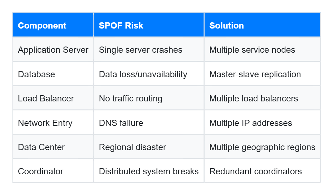
Core Principles
- Identify critical components — What would crash the system?
- Add redundancy — Multiple copies of everything important
- Handle coordination — Make the orchestration layer resilient too
- Test in production — Use chaos engineering (if you’re Netflix-level)
- Accept costs — Redundancy requires more resources
The Math
Each layer of redundancy dramatically improves reliability:
- 1 node: P failure rate
- 2 nodes: P² failure rate
- 3 nodes: P³ failure rate
Even modest redundancy (2x) provides huge reliability gains.
Final Thoughts
Building resilient systems is about identifying every critical component and asking: “What happens if this fails?”
If the answer is “everything breaks,” you’ve found a single point of failure. The solution is almost always redundancy with proper failover mechanisms.
The challenge isn’t knowing you need redundancy — it’s implementing the coordination, consistency, and failover logic that makes redundancy actually work.
Remember: In distributed systems, it’s not about IF components fail, it’s about WHEN they fail. Design accordingly.
메타데이터
- post_id
- ff50daea858d
- slug
- system-design-basics-avoiding-single-points-of-failure-in-distributed-systems-ff50daea858d
- url
- https://medium.com/@onlinelearner01learn/system-design-basics-avoiding-single-points-of-failure-in-distributed-systems-ff50daea858d
- canonical_url
- https://medium.com/@onlinelearner01learn/system-design-basics-avoiding-single-points-of-failure-in-distributed-systems-ff50daea858d
- author_url
- https://medium.com/@onlinelearner01learn
- status
- ok
- fetched_at
- 2026-06-21 15:33:18