Adaptive reuse for cities
Guan-Yi Siao | Shao-Wei Wang | Meng-Syun Sung | Chih-Chia Huang | Nien Lee | Generative Design | Fall 2025 | GSAPP
Adaptive reuse for cities
Guan-Yi Siao | Shao-Wei Wang | Meng-Syun Sung | Chih-Chia Huang | Nien Lee | Generative Design | Fall 2025 | GSAPP
Introduction
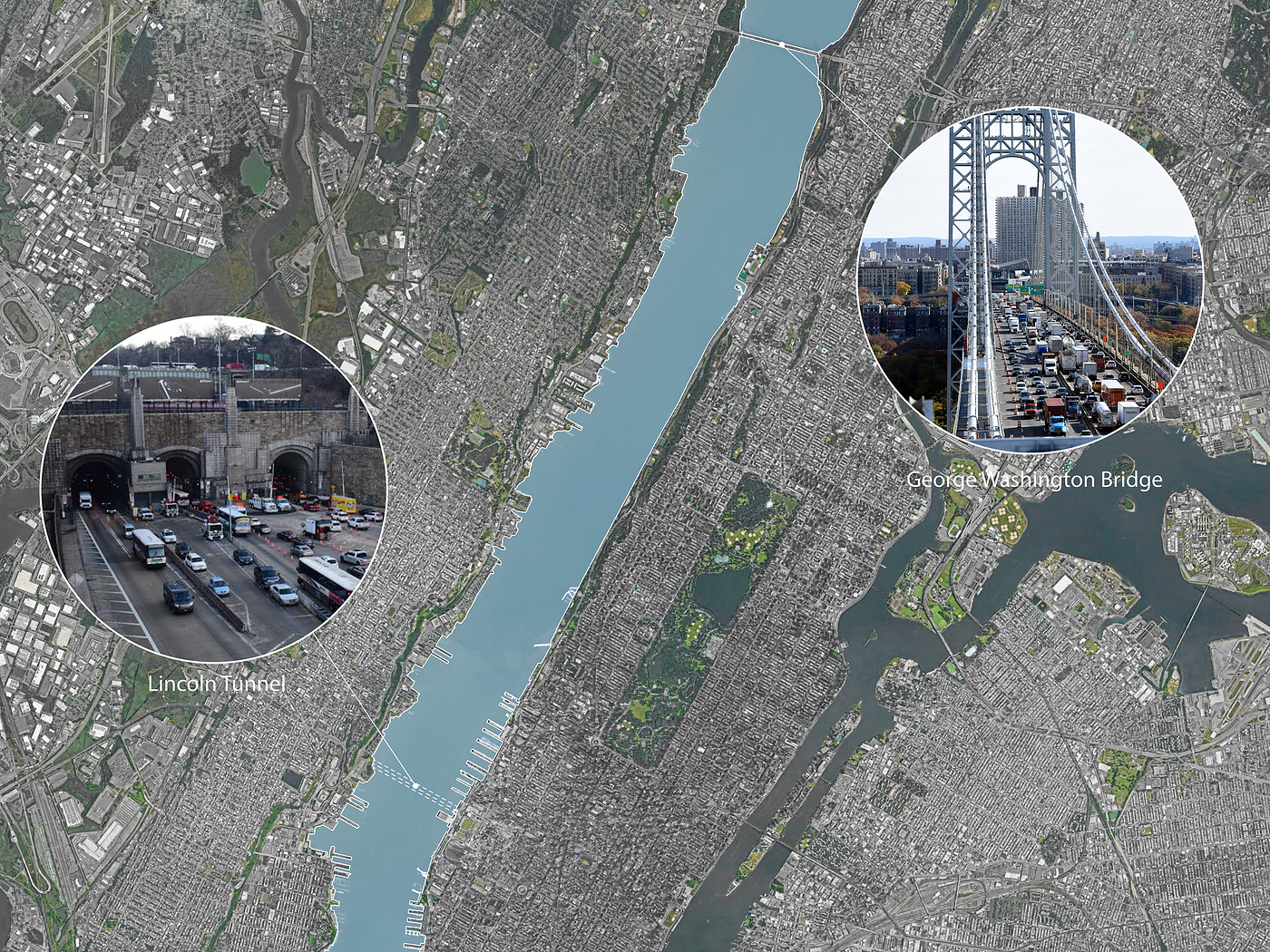
Addressing the high vacancy rates in post-pandemic New York, this project explores the potential of repurposing office buildings into residential units. By analyzing successful precedents from industry leaders like SOM, we developed a generative planning algorithm. Designed for both developers and architects, this tool expedites the design workflow, allowing users to efficiently iterate through spatial configurations for complex conversion scenarios.
AI-generated webpage to test algorithmic logic.
Minimal Skeleton Layout Generator Logic Specification

- System Overview
This system is an automated architectural layout engine based on “Rule-Based” logic and “Monte Carlo Simulation.”
Its core task is to simulate hundreds of distinct room configurations within an extremely short timeframe (milliseconds), automatically selecting the solution that offers optimal spatial efficiency and the most rational circulation. The system’s operation strictly adheres to physical collision avoidance principles and user-defined geometric parameters.
2. Single Generation Logic
When the system generates each floor plan layout, it strictly adheres to the physical sequence of architectural design, progressing from structure to interior elements. It executes the following three phases in order:
2–1 Spatial Anchoring
Before commencing the room layout, the system first anchors “immovable” objects onto the site to establish the framework:
2–2 Cores
Based on user-input coordinates, the system prioritizes the placement of elevator shafts and stairwells. These are the highest-priority elements and cannot be overlapped.
2–3 Custom Reserved Zones (Special Spaces)
Places user-defined special spaces (such as light wells or mechanical rooms). These areas are designated as “exclusion zones” (no-build zones), requiring all subsequently generated rooms to navigate around them.
3–1 Scanning Sequence
The system does not scatter rooms randomly; instead, it simulates a construction sequence, growing inward from the four edges of the site in a specific order:
- Top Pass: Along the top boundary, arranged from left to right.
- Bottom Pass: Along the bottom boundary, arranged from left to right.
- Left Pass: Along the left boundary, arranged from bottom to top.
- Right Pass: Along the right boundary, arranged from top to bottom.
- (If a loop corridor is enabled, this process is repeated for both sides of the inner corridor loop.)
3–2 Intelligent Selection & Weighting
At each scanning point, the system must decide: “Which room typology should be placed here?”
3–3 Weighted Selection Mechanism
Based on user-defined ratios (e.g., Type A 40%, Type B 30%…), the system determines the room type for the current attempt via a probabilistic wheel.
3–4 Dimension Fine-Tuning
For the selected room type, the system tests three different size variants, prioritizing the depth dimension that best fits the current boundary.
3–5 Physical Collision Detection
Before “building” (placing) a room, the system performs rigorous physical checks:
3–6 Overlap Check
Does the new room overlap with existing cores, corridors, reserved zones, or already placed rooms?
3–7 Micro-Stepping Search
If the room cannot be placed at the current position (e.g., it is blocked by a column), the system does not immediately discard it. Instead, it shifts the position slightly (e.g., nudging 20cm to the right) and retries placement. This simulates the process of a designer fine-tuning lines on a drawing, significantly increasing the spatial fill rate.
4–1 Circulation Planning
Circulation acts as the vascular system connecting spaces. Once the structural framework is established, the system immediately generates the pathway network:
4–2 Main Loop Construction
If the user enables the “Loop Corridor” option, the system reserves a rectangular “square-loop” corridor within the site, calculated based on the depth of the rooms.
4–3 Radial Connections
- Ray Casting: The system initiates from the center point of each core, projecting virtual rays in the four cardinal directions (up, down, left, right).
- Path Validation: If a ray’s path is not obstructed by a “Custom Reserved Zone” and successfully reaches the main loop or the site boundary, the system automatically generates a straight corridor along that path.
- Connectivity: This ensures that regardless of the core’s location, it connects to the primary circulation system via the shortest possible route.
5. The Optimization Loop
Phases 2 through 4 described above generate only a “single” stochastic layout draft. To guarantee the quality of the final output, the system encapsulates this process within an outer “Competition Mechanism”:
5–1 Simulation & Competition
Mass Generation: The system rapidly iterates through the aforementioned “Phases 1 to 3” 200 times in the background. Due to the stochastic nature of the packing strategy, each generated outcome is distinct.
5–2 Real-Time Scoring
For each draft layout, the system calculates a “Void Space Ratio.”
- Formula Concept: Total Site Area — (All Rooms + Corridors + Cores + Custom Spaces) = Wasted Interstices (Gaps).
5–3 Selection of the Fittest
The system continuously monitors the performance of these 200 draft iterations.
5–4 Intelligent Termination Mechanism
- Once a draft’s Void Space Ratio drops below 10% (implying a Space Utilization Rate > 90%), the system designates it as an “Optimal Design,” immediately halts further computation to conserve computational resources, and outputs the result.
- If the threshold is not met after the full 200 iterations, the system forces the selection of the highest-scoring layout among the generated set.
6. Visualization and Data Output
Once the “Champion Solution” is finalized, the system executes the final phase of interpretation:
Layout Rendering: Converts abstract mathematical coordinates into color blocks on the Canvas.
- Orange / Yellow / Blue / Green: Represent different Room Typologies.
- Grey: Represents Cores.
- Purple: Represents Custom Reserved Zones.
Methodology

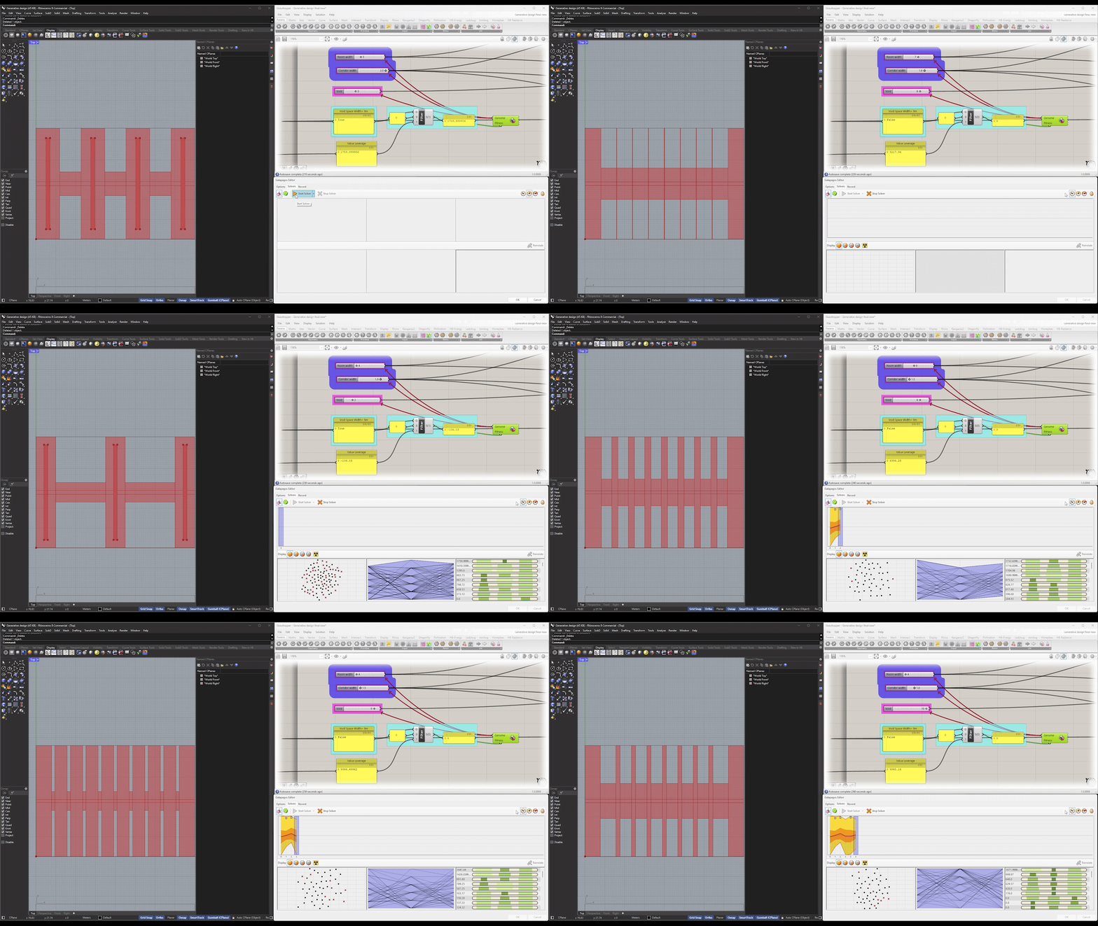
To simplify the logic of our computation, we returned to a fundamental question: What building width allows for the most efficient unit placement? Our approach begins with simple geometric cuts to identify the optimal void strategy, which then guides the room layout generation.
Regarding width, typical residential unit depth rarely exceeds 10 meters. Assuming a double-loaded corridor — the most efficient arrangement — we define the maximum effective width as two room depths plus the corridor width, referred to as the ‘Efficiency Width’ (Zone A).
The segments connecting each Zone A are defined as Zone B. Zone B follows the same depth logic, but its length (the void width) is determined by the New York Zoning Resolution, which requires interior courts to be at least 30 feet wide to allow for legal window openings. With room, corridor, and void widths defined, we can then evaluate which void-cutting strategy performs best.
Generative Result

· Import Initial Building Boundary: Extract the longest edge of the boundary.

· Define 3 Parameter Factors: Room Width (4–10m), Corridor Width (1.5–2.5m), and Quantity of Single-side Voids.

· Subdivision: Subdivide the building’s long edge based on these three factors.

· Generation: Obtain Corridor Locations, Void Locations, and the New Building Plan.

· Scoring: Import Residential Scoring Parameters.
· Optimization: Execute Galapagos Multi-Objective Optimization to find the best solution.
Conclusion
In response to the urgent demand for housing and the surplus of vacant office space in post-pandemic New York, this study establishes a rigorous methodology for efficient conversion. By analyzing the “Efficiency Width” and strictly adhering to NYC light-and-air zoning requirements, the generative algorithm proves that complex deep-floorplate buildings can be systematically reconfigured into viable residential communities. The success of the Minimal Skeleton Layout Generator lies in its ability to balance quantitative optimization — such as minimizing void space — with the qualitative needs of architectural circulation. This tool serves as a critical proof-of-concept, illustrating how algorithmic logic can unlock the latent potential of existing urban infrastructure.
메타데이터
- post_id
- 01932fd40668
- slug
- adaptive-reuse-for-cities-01932fd40668
- url
- https://medium.com/generative-design-course/adaptive-reuse-for-cities-01932fd40668
- canonical_url
- https://medium.com/generative-design-course/adaptive-reuse-for-cities-01932fd40668
- author_url
- https://medium.com/@ms7309
- status
- ok
- fetched_at
- 2026-06-15 20:49:13