What Actually Happens When You Call HAL_GPIO_WritePin()?
A beginner-friendly investigation into how a single STM32 HAL function travels from your application code to the GPIO hardware, revealing…
What Actually Happens When You Call HAL_GPIO_WritePin()?
A beginner-friendly investigation into how a single STM32 HAL function travels from your application code to the GPIO hardware, revealing the software, registers, and hardware working together beneath the abstraction.
“Every abstraction hides a mechanism. Great engineers eventually look underneath.”
What You’ll Learn
By the end of this article, you’ll be able to:
- Explain what a GPIO peripheral really is.
- Understand why the STM32 Hardware Abstraction Layer (HAL) exists.
- Trace
HAL_GPIO_WritePin()from your application code to the GPIO hardware. - Understand the purpose of memory-mapped registers involved in GPIO control.
- Explain why STM32 uses the
BSRRregister for GPIO writes. - Compare HAL-based programming with direct register programming.
- Build a stronger intuition for how software interacts with hardware inside an embedded system.
Chapter 1 — The Hook
If you’ve spent even a few hours working with an STM32 microcontroller, you’ve probably written this line of code:
HAL_GPIO_WritePin(GPIOA, GPIO_PIN_5, GPIO_PIN_SET);
A single function call.
The LED turns on.
The program works.
You smile because your first hardware interaction was successful.
And then, like most beginners — including me — you move on to the next lesson.
For a long time, I treated HAL_GPIO_WritePin() as just another function provided by the STM32 HAL library. It worked exactly as expected, and honestly, that felt like enough.
But one day, a simple question changed the way I looked at embedded systems:
What actually happens after this function is called?
Does this function somehow communicate directly with the GPIO pin?
Does the microcontroller execute some hidden “HAL magic”?
Or is something much simpler happening beneath the abstraction?
Those questions led me down a path I hadn’t explored before.
Instead of treating the HAL as a black box, I decided to investigate what really happens between writing a single line of C code and seeing an LED turn on.
That investigation took me through the STM32 HAL source code, GPIO registers, memory-mapped peripherals, and eventually to the hardware itself.
Along the way, I realized something important:
The HAL isn’t hiding the hardware — it is simply providing a cleaner way to access it.
That realization completely changed how I approach embedded programming.
In this article, we’ll follow the complete journey of a single function call — from your application code, through the HAL driver, into the GPIO registers, and finally to the silicon that changes the voltage on a physical pin.
If you’ve ever wondered what lies beneath HAL_GPIO_WritePin(), this investigation is for you.
Chapter 2 — Before We Follow the Function Call, We Need to Know Where It Goes
Every investigation needs a starting point.
Ours begins with a simple question.
When we write:
HAL_GPIO_WritePin(GPIOA, GPIO_PIN_5, GPIO_PIN_SET);where does this function actually send that request?
The answer is not “to the LED.”
Before the LED changes state, the request travels through several layers inside the microcontroller.
Understanding those layers is the key to understanding what the HAL is really doing.
The Microcontroller Is More Than Just a CPU
When people first learn embedded systems, it’s easy to imagine a microcontroller as a tiny CPU with some pins attached to it.
In reality, a microcontroller is an entire computer on a single chip.
Inside an STM32 device you’ll find several hardware blocks working together:
- A CPU that executes your program.
- Flash memory that stores your code.
- SRAM for variables and the stack.
- Timers for precise timing.
- Communication peripherals such as UART, SPI, and I²C.
- GPIO peripherals that connect the processor to the outside world.
Each of these hardware blocks has a specific job.
The CPU doesn’t directly control an LED.
Instead, it asks another hardware block — the GPIO peripheral — to do it.
This separation keeps the microcontroller organized and allows each peripheral to specialize in its own task.
Meet the GPIO Peripheral
Earlier we learned that GPIO stands for General Purpose Input/Output.
But here’s an important realization:
GPIO is not just a physical pin.
The pin you see on the microcontroller package is only the final connection to the outside world.
Behind that pin is dedicated hardware called the GPIO peripheral.
Think of the GPIO peripheral as a small hardware controller responsible for managing every GPIO pin in its port.
It decides things such as:
- Is this pin an input or an output?
- Should the output be HIGH or LOW?
- Should an internal pull-up resistor be enabled?
- Should this pin operate as a normal GPIO or an alternate function like UART or SPI?
The CPU doesn’t answer these questions directly.
It communicates with the GPIO peripheral, and the GPIO peripheral controls the pin.
How Does the CPU Talk to the GPIO Peripheral?
Now we arrive at an interesting question.
If the GPIO peripheral is a separate hardware block, how does the CPU communicate with it?
Does it send messages?
Does it call another processor?
Does it use some hidden protocol?
The answer is surprisingly elegant.
The CPU communicates with peripherals by reading and writing memory addresses.
In other words, from the CPU’s point of view, controlling hardware looks very similar to reading from or writing to memory.
This design is known as memory-mapped I/O, and it’s one of the most fundamental ideas in embedded systems.
We’ll explore exactly how it works in the next section because it forms the bridge between a simple HAL function and the hardware that ultimately changes the voltage on a GPIO pin.
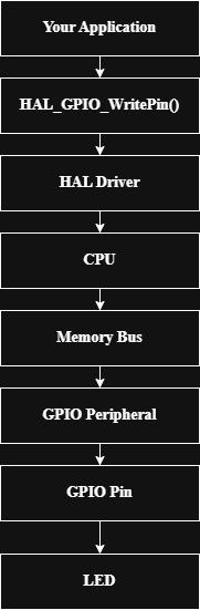
“A high-level view of the path taken before a GPIO pin changes state.”
Chapter 3 — Memory-Mapped I/O: How the CPU Talks to Hardware
In the previous chapter, we discovered that the CPU doesn’t control a GPIO pin directly. Instead, it communicates with a dedicated hardware block called the GPIO peripheral.
That naturally raises another question:
How does the CPU communicate with the GPIO peripheral?
At first, I imagined there might be a special communication protocol between the CPU and the hardware. The reality is much simpler — and, in my opinion, much more elegant.
The CPU communicates with hardware peripherals by reading from and writing to specific memory addresses.
This design is known as Memory-Mapped Input/Output (Memory-Mapped I/O or MMIO), and it is one of the fundamental concepts behind modern embedded systems.
One Address Space for Everything
When we first learn programming, we usually think of memory as a place where variables are stored.
For example:
int temperature = 25;The compiler stores the value 25 somewhere in RAM, and the CPU accesses it through a memory address.
But in a microcontroller, not every address points to RAM.
Some addresses are connected to hardware peripherals instead.
That means writing to certain memory locations doesn’t change a variable — it changes the behaviour of hardware.
For example:
- One address might control a GPIO pin.
- Another might configure a timer.
- Another might start a UART transmission.
To the CPU, these operations all look the same: read from or write to an address.
The difference lies in what is connected to that address.
A Different Way to Think About Hardware
One idea helped me understand this concept.
Imagine a large office building.
Every room has its own room number.
Some rooms are offices.
Some are meeting rooms.
Some are laboratories.
The room number tells you where to go, while the purpose of the room depends on what exists behind the door.
Memory addresses work in a similar way.
Some addresses lead to RAM.
Others lead to Flash memory.
Others are connected directly to hardware peripherals such as GPIO, timers, UART, SPI, or I²C.
From the CPU’s perspective, it is simply accessing an address.
What happens next depends on what hardware is mapped to that address.
The GPIO Peripheral Has Its Own Registers
The GPIO peripheral doesn’t understand C code or HAL functions.
Instead, it contains a collection of registers.
A register is a small storage location inside the hardware that controls a specific aspect of the peripheral.
For example, one register decides whether a pin acts as an input or an output.
Another register stores whether the output should be HIGH or LOW.
Another enables pull-up or pull-down resistors.
Each register has its own memory address.
When the CPU writes to one of these addresses, it is actually changing the state of the GPIO hardware.
This is the bridge between software and the physical world.
Where Does HAL Fit Into This?
At this point, something important becomes clear.
When we write:
HAL_GPIO_WritePin(GPIOA, GPIO_PIN_5, GPIO_PIN_SET);the HAL isn’t sending a message to the GPIO peripheral.
Instead, the HAL eventually writes a value into one of the GPIO registers.
The GPIO peripheral detects that change and updates the voltage on the corresponding pin.
In other words, the HAL doesn’t replace the hardware — it provides a cleaner way to access it.
That realization completely changed how I thought about embedded software.
Looking Ahead
Now that we understand how the CPU communicates with hardware, we’re ready to examine the hardware itself.
The GPIO peripheral contains several registers, each responsible for a different part of pin configuration and control.
Before tracing HAL_GPIO_WritePin(), we need to understand what these registers are and why they exist.
That’s where our investigation takes us next.
Engineering Pause
Before moving on, think about this question:
If writing to a memory address can change the voltage on a physical pin, what must exist inside the GPIO peripheral to make that happen?
We’ll answer that in the next chapter by opening up the GPIO peripheral and exploring the registers that control every GPIO pin.
Chapter 4 — Opening the GPIO Peripheral: Understanding the Registers Behind Every Pin
Now we know that the CPU communicates with the GPIO peripheral by reading from and writing to memory-mapped registers.
But what exactly are these registers?
More importantly, which register does HAL_GPIO_WritePin() actually modify?
To answer that, we need to step inside the GPIO peripheral itself.
A Peripheral Is More Than a Single Register
When I first started learning embedded systems, I imagined a GPIO peripheral as a single block of hardware with one register controlling everything.
The reality is much more organized.
Each GPIO peripheral contains multiple registers, and every register has a specific responsibility.
Rather than storing application data like RAM, these registers act as configuration and control points for the hardware.
Together, they define how every GPIO pin behaves.
Think of Registers as Control Panels
Imagine you’re operating a satellite ground station.
Instead of having one giant switch that controls the entire station, you have several dedicated control panels.
One panel configures the antenna.
Another controls the transmitter.
Another monitors system health.
Each panel has a clear responsibility.
GPIO registers work in much the same way.
Instead of one large register controlling every aspect of a GPIO pin, STM32 divides the responsibilities across several specialized registers.
This design makes the hardware easier to organize, understand, and extend.
The Most Important GPIO Registers
Although an STM32 GPIO peripheral contains several registers, a few are especially important for understanding how a pin is configured and controlled.
MODER (Mode Register)
This register determines how a pin operates.
For every GPIO pin, MODER specifies whether it functions as:
- Input
- Output
- Alternate Function
- Analog
Without configuring the mode correctly, the pin cannot perform its intended role.
OTYPER (Output Type Register)
Once a pin is configured as an output, the OTYPER register defines how that output is electrically driven.
For most beginner applications, the default push-pull configuration is sufficient.
Open-drain outputs become important when multiple devices share a communication line, such as on an I²C bus.
PUPDR (Pull-Up/Pull-Down Register)
Digital input pins should never be left electrically “floating.”
A floating input can randomly change between HIGH and LOW because of electrical noise.
The PUPDR register allows us to enable:
- Internal pull-up resistors
- Internal pull-down resistors
- No pull resistor
These internal resistors help ensure that an input pin always has a defined logic level.
IDR (Input Data Register)
When software wants to know whether an input pin is HIGH or LOW, it reads the Input Data Register (IDR).
This register reflects the current electrical state of the GPIO input pins.
In other words, the CPU doesn’t read the voltage directly — it reads the value stored in the IDR register.
ODR (Output Data Register)
The Output Data Register (ODR) stores the desired output state of GPIO pins.
Writing a HIGH or LOW value into ODR changes the output state of the corresponding pin.
At first glance, this seems like the obvious register for controlling an LED.
However, STM32 provides another register that performs this task more safely and efficiently.
We’ll discover why shortly.
BSRR (Bit Set/Reset Register)
This is the register that plays the starring role in our investigation.
Rather than rewriting the entire output register, the Bit Set/Reset Register (BSRR) allows software to set or clear individual GPIO pins with a single write operation.
This makes GPIO updates both efficient and safe, especially when interrupts or multiple software tasks are involved.
As we’ll soon see, HAL_GPIO_WritePin() ultimately writes to this register—not directly to ODR.
Seeing the Bigger Picture
At this point, the GPIO peripheral should feel less mysterious.
Instead of being a black box, it is a collection of specialized registers, each responsible for a different aspect of GPIO operation.
When we configure a GPIO pin, we modify configuration registers such as MODER or PUPDR.
When we read a button, we access IDR.
And when we change the state of an output pin, we eventually write to BSRR.
Understanding these responsibilities is essential because the HAL library is simply manipulating these registers on our behalf.
The abstraction is becoming thinner with every step.
Engineering Pause
Before moving on, consider this question:
If the Output Data Register (ODR) can already control GPIO outputs, why did STMicroelectronics introduce another register called BSRR?
At first, it seems redundant.
In the next chapter, we’ll discover that this design decision solves a subtle but important problem in embedded systems — one that only becomes obvious when software has to operate reliably under real-world conditions.

“Inside the STM32 GPIO Peripheral ; Each GPIO register has a dedicated responsibility. Together, they allow software to configure, read, and control GPIO pins.”
Chapter 5 — Following the Function Call: What Really Happens Inside HAL_GPIO_WritePin()?
Everything we’ve learned so far has prepared us for this moment.
We now understand:
- What a GPIO peripheral is.
- How the CPU communicates with hardware.
- Why peripherals expose memory-mapped registers.
- Which registers exist inside the GPIO peripheral.
Now it’s finally time to answer the question that inspired this entire investigation.
What actually happens when we call
HAL_GPIO_WritePin()?
Instead of guessing, let’s follow the function exactly as the processor does.
Step 1 — Our Application Makes the Request
Our journey begins in the application code.
A simple LED blink program might contain the following line:
HAL_GPIO_WritePin(GPIOA, GPIO_PIN_5, GPIO_PIN_SET);At first glance, this appears to be a complete operation.
But in reality, it is only a function call.
The CPU has not changed the GPIO pin yet.
Instead, it begins executing the instructions inside the HAL library.
This is no different from calling any other C function.
The only difference is that this particular function eventually interacts with hardware.
Step 2 — Jumping Into the HAL Driver
The declaration of the function is found in the HAL header file, while its implementation lives inside the STM32 HAL driver source code.
When we open the driver source, we discover that HAL_GPIO_WritePin() is surprisingly small.
Rather than performing dozens of complex operations, its job is simply to validate the parameters and write to the appropriate GPIO register.
One of the most interesting discoveries during this investigation was realizing how little “magic” actually exists inside the HAL.
The abstraction is intentionally thin.
Its purpose is not to replace the hardware — it is to provide a safer and more readable interface for accessing it.
Step 3 — Checking the Requested Pin State
The function first checks whether the requested output state is HIGH or LOW.
Conceptually, the logic looks like this:
if (PinState == GPIO_PIN_SET)
{
    // Set the pin
}
else
{
    // Reset the pin
}
This decision determines which half of the Bit Set/Reset Register (BSRR) will be written.
Although this logic is simple, it highlights an important principle of embedded software: even high-level APIs ultimately reduce to straightforward hardware operations.
Step 4 — Writing to the GPIO Register
This is the moment where software crosses into hardware.
If the requested state is HIGH, the HAL writes to the lower half of the GPIO BSRR register.
If the requested state is LOW, it writes to the upper half.
The GPIO peripheral continuously monitors this register.
As soon as the write occurs, the hardware updates the output driver connected to the selected GPIO pin.
No additional software intervention is required.
The peripheral performs the rest of the work automatically.
Step 5 — The Voltage on the Pin Changes
Once the GPIO peripheral processes the register write, the electrical state of the output pin changes.
If the pin is driven HIGH, the voltage rises to the microcontroller’s logic HIGH level.
If it is driven LOW, the voltage falls close to ground.
For an LED connected to that pin, this electrical change determines whether current flows through the circuit.
If current flows, the LED lights up.
If it does not, the LED remains off.
What began as a single line of C code has now become a physical electrical event.
The Entire Journey
Looking back, the complete path is surprisingly elegant:
Application Code
        │
        ▼
HAL_GPIO_WritePin()
        │
        ▼
HAL Driver
        │
        ▼
GPIO BSRR Register
        │
        ▼
GPIO Peripheral
        │
        ▼
Output Driver
        │
        ▼
Physical GPIO Pin
        │
        ▼
LED Turns ON
One line of software.
One register write.
One hardware response.
One visible result.
A Different Perspective
Before starting this investigation, I thought of HAL_GPIO_WritePin() as the operation that turned an LED on.
Now I see it differently.
The function itself never touches the LED.
It doesn’t generate voltage.
It doesn’t directly control the GPIO pin.
Its only responsibility is to write the correct value into the correct hardware register.
Everything after that is handled by the GPIO peripheral itself.
Understanding this distinction changed the way I think about hardware abstraction.
The HAL isn’t performing the hardware operation — it is instructing the hardware what to do.
Engineering Pause
We’ve followed the function all the way to the BSRR register.
But one question still remains unanswered:
Why does STM32 use the BSRR register instead of simply writing to the Output Data Register (ODR)?
The answer involves one of the most important concepts in reliable embedded programming: atomic operations.
That will be the focus of the next chapter.

“HAL_GPIO_WritePin() from Software to Hardware”
Chapter 6 — Why Doesn’t HAL_GPIO_WritePin() Write to ODR? Understanding the BSRR Register
During our investigation, we discovered that HAL_GPIO_WritePin() doesn't directly modify the Output Data Register (ODR).
Instead, it writes to another register called the Bit Set/Reset Register (BSRR).
At first, this seemed unnecessary.
After all, if the ODR already stores the output state of every GPIO pin, why introduce another register that appears to do the same job?
The answer lies in one word:
Atomicity.
Understanding this concept explains one of the smartest design decisions in the STM32 GPIO peripheral.
The Problem with ODR
Let’s imagine we want to turn ON only PA5.
One possible approach would be to modify the Output Data Register.
Conceptually, the CPU would perform three steps:
- Read the current value stored in ODR.
- Modify only the bit corresponding to PA5.
- Write the updated value back to ODR.
This sequence is commonly called a Read–Modify–Write operation.
Although it works in many situations, it introduces a subtle problem.
Between the read and the write, something else might happen.
Imagine an Interrupt Occurs
Suppose your program is controlling several GPIO pins.
While your application is updating PA5, an interrupt occurs and another piece of software changes a different GPIO pin using the same ODR register.
When the interrupt finishes, your original code continues and writes its old copy of the register back to ODR.
The modification made by the interrupt is now lost.
Neither piece of software is incorrect.
The problem is that both relied on reading and rewriting the same register.
This type of issue becomes increasingly important in systems running interrupts, RTOS tasks, or multiple software modules.
STM32’s Solution: The BSRR Register
Instead of requiring software to perform a Read–Modify–Write sequence, STM32 provides the Bit Set/Reset Register (BSRR).
Rather than rewriting the entire output register, the CPU simply writes a command to the BSRR.
The GPIO peripheral interprets that command and updates only the requested pin.
No preliminary read is required.
No existing bits need to be modified in software.
The operation completes with a single register write.
Understanding the Layout of BSRR
The BSRR register is 32 bits wide.
It is divided into two independent halves.
31                     16 15                      0
+------------------------+-------------------------+
| Reset Bits             | Set Bits               |
+------------------------+-------------------------+- Writing a 1 to the lower 16 bits sets the corresponding GPIO pin HIGH.
- Writing a 1 to the upper 16 bits resets the corresponding GPIO pin LOW.
- Writing 0 has no effect.
This design allows the software to control individual pins without disturbing the state of any other pin.
An Example
Suppose we want to set PA5 HIGH.
Instead of reading and modifying ODR, the HAL writes a value that tells the GPIO peripheral:
“Set bit 5.”
The peripheral performs the operation immediately.
Similarly, to reset PA5, the HAL writes to the upper half of the BSRR register.
Again, only the requested pin changes.
Every other GPIO pin remains untouched.
Why Engineers Prefer BSRR
As I learned more about this register, I realized that BSRR offers several important advantages.
It provides:
- Atomic updates, reducing the chance of race conditions.
- No Read–Modify–Write sequence, simplifying the operation.
- Improved reliability when interrupts or multiple software tasks access GPIO.
- Better efficiency, since only a single register write is required.
For a beginner blinking an LED, these benefits may not seem important.
But in real embedded systems — where multiple peripherals, interrupts, and tasks operate simultaneously — they become essential.
Looking Back at HAL_GPIO_WritePin()
Earlier, we saw that the HAL eventually writes to the BSRR register.
Now we understand why.
The developers of the STM32 HAL didn’t choose BSRR by accident.
They chose it because it is the safest and most reliable way to update individual GPIO pins.
Sometimes, the most interesting engineering decisions are the ones hidden inside a single line of code.
Engineering Pause
At this point, we’ve followed the software all the way to the GPIO hardware.
But one question remains:
If HAL ultimately performs a simple register write, could we write the same operation ourselves without using HAL?
The answer is yes.
In the next chapter, we’ll implement the same GPIO operation using direct register programming and compare it with the HAL approach.

”ODR vs BSRR: Two Different Ways to Control a GPIO Pin ; BSRR avoids the Read–Modify–Write sequence, making GPIO updates atomic and more reliable.”
Chapter 7 — Beyond HAL: Writing to the GPIO Register Directly
At this point in our investigation, we’ve followed HAL_GPIO_WritePin() all the way to the GPIO peripheral.
We’ve seen that the HAL eventually writes to the Bit Set/Reset Register (BSRR) to change the state of a GPIO pin.
That naturally raises another question:
If the HAL ultimately performs a register write, do we actually need the HAL to control a GPIO pin?
The answer is no.
We can perform the same operation ourselves by writing directly to the appropriate hardware register.
Understanding both approaches helps us appreciate what the HAL provides — and what it deliberately leaves unchanged.
Writing to the Register Ourselves
Suppose we want to set PA5 HIGH.
Using the HAL, we write:
HAL_GPIO_WritePin(GPIOA, GPIO_PIN_5, GPIO_PIN_SET);Behind the scenes, the HAL eventually performs an operation equivalent to writing to the GPIO BSRR register.
At the register level, the same action can be expressed as:
GPIOA->BSRR = GPIO_BSRR_BS5;Likewise, resetting PA5 can be written as:
GPIOA->BSRR = GPIO_BSRR_BR5;Although these statements look very different, they ultimately produce the same hardware behaviour.
The GPIO peripheral receives a command through the BSRR register and updates the electrical state of PA5.
Two Different Levels of Abstraction
The difference between these two approaches is not what the hardware does.
The difference is who performs the work.
With HAL:
- The library checks the parameters.
- It provides a readable API.
- It hides register-level details.
- It improves portability across STM32 families.
With direct register programming:
- The programmer accesses the hardware registers directly.
- The code is shorter.
- The programmer has complete control.
- The programmer is responsible for correctness.
In both cases, the destination is exactly the same: the GPIO peripheral.
Which Approach Is Better?
When I first learned register programming, I assumed it must always be superior because it operates closer to the hardware.
After studying how the HAL works, my perspective changed.
The choice isn’t about one method being universally better than the other.
Instead, it depends on the problem you’re trying to solve.
For many applications, the HAL provides clear, maintainable, and reliable code that is easy to understand and debug.
For applications with strict timing requirements or hardware-specific optimizations, direct register programming may provide greater control.
Professional embedded engineers often use both approaches.
They rely on the HAL where it improves readability and development speed, and they work directly with registers when precise control or maximum performance is required.
Looking at Both Approaches Together
One observation stood out during this investigation.
Although the two code snippets appear very different, they eventually converge at the same point.
Both paths end with a write to the GPIO hardware.
The abstraction changes.
The destination does not.
That realization helped me see the HAL in a different light.
It isn’t a replacement for register programming.
It is a carefully designed interface built on top of it.
A Practical Lesson
One of the biggest lessons I learned while writing this article is that understanding the HAL and understanding registers are not competing skills.
In fact, they complement each other.
Knowing the HAL allows you to develop software efficiently.
Knowing the registers allows you to understand what the software is actually doing.
Together, they provide a much stronger foundation for embedded systems engineering than relying on either one alone.
Engineering Pause
We’ve now traced the software from application code all the way to the hardware registers.
Before concluding our investigation, let’s step back and compare the complete journey.
What did we actually learn by following a single function call from C code to silicon?
That reflection will form the conclusion of this investigation.

“HAL vs Direct Register Programming ; Both approaches ultimately reach the same GPIO hardware. The difference lies in the level of abstraction, not the final destination.”
Chapter 8 — Looking Back: What a Single Function Call Taught Me About Embedded Systems
When I began writing this article, my goal was simple.
I wanted to answer one question:
What actually happens when we call
HAL_GPIO_WritePin()?
At first, I expected the answer to be a straightforward explanation of a library function.
Instead, following that single function call revealed an entire chain of interactions between software and hardware.
What seemed like one line of C code turned out to be a journey through multiple layers of an embedded system.
Every Layer Has a Responsibility
One of the biggest lessons from this investigation is that embedded software is built in layers.
Each layer has a clear responsibility.
Our application expresses what we want to do.
The HAL translates that request into hardware operations.
The CPU executes instructions.
The GPIO peripheral interprets register writes.
Finally, the physical pin changes its electrical state.
None of these layers works alone.
Each one depends on the others to transform software into a real-world action.
Understanding these responsibilities made the entire system feel much less mysterious.
Abstraction Is Not the Enemy
Before starting this investigation, I thought of the Hardware Abstraction Layer as something that hid the “real” hardware.
Now I see it differently.
The HAL does not replace the hardware.
It simply provides a cleaner interface for accessing it.
Every HAL function ultimately relies on the same registers that we could access directly ourselves.
The abstraction changes how we write the code.
It does not change what the hardware ultimately does.
That realization gave me a much greater appreciation for well-designed software abstractions.
Asking “Why?” Changes Everything
Looking back, the most valuable part of this investigation wasn’t learning about the BSRR register or memory-mapped I/O.
It was developing the habit of asking why.
Why does the HAL exist?
Why are peripherals memory-mapped?
Why does STM32 use BSRR instead of ODR?
Every answer uncovered another layer of understanding.
Instead of memorizing APIs, I found myself understanding the engineering decisions behind them.
That shift — from using a function to understanding its design — is something I hope to carry into every future embedded project.
A Small Function, A Bigger Lesson
HAL_GPIO_WritePin() is one of the simplest functions in the STM32 HAL library.
Yet investigating it introduced concepts that appear throughout embedded systems:
- Hardware abstraction.
- Memory-mapped I/O.
- Peripheral registers.
- Atomic register operations.
- The relationship between software and hardware.
Sometimes the simplest functions are the best places to begin learning, because they reveal ideas that scale to much larger and more complex systems.
An Invitation to Explore Further
If there’s one idea I’d like readers to take away from this article, it’s this:
Don’t stop at making the code work. Spend some time understanding why it works.
Every abstraction is built on top of another layer.
Following those layers is one of the most rewarding parts of learning embedded systems.
You don’t need to investigate every library function.
But every now and then, choosing one simple function and tracing it all the way to the hardware can teach far more than simply reading its documentation.
Engineering Reflection
Before finishing this article, I’d like to leave you with one final question.
The next time you call a function like:
HAL_UART_Transmit()or
HAL_SPI_Transmit()pause for a moment and ask yourself:
What is actually happening underneath this abstraction?
That single question can turn an ordinary programming exercise into an engineering investigation.
Chapter 9 — References, Further Reading, and What’s Next
Every investigation builds on the work of others.
While writing this article, I referred to official documentation and trusted engineering resources to verify concepts rather than relying on assumptions. If you’re interested in exploring these topics further, the following references are an excellent place to start.
References
Official Documentation
- STM32 Reference Manual for your specific STM32 microcontroller family (for example, STM32F4 Reference Manual).
- STM32 HAL Driver source code (
stm32fxxx_hal_gpio.c). - STM32 HAL User Manual.
- CMSIS (Cortex Microcontroller Software Interface Standard) documentation.
These official resources provide the most accurate description of GPIO peripherals, memory-mapped registers, and the HAL implementation.
Books
- The Definitive Guide to ARM® Cortex®-M3 and Cortex®-M4 Processors by Joseph Yiu.
- Making Embedded Systems by Elecia White.
- Embedded Systems: Introduction to ARM Cortex-M Microcontrollers by Jonathan Valvano.
These books helped deepen my understanding of embedded systems concepts beyond simply learning APIs.
Concepts Worth Exploring Next
If this article sparked your curiosity, these topics are natural next steps:
- Memory-mapped I/O in greater detail.
- Interrupts and exception handling.
- Timers and counters.
- UART communication.
- SPI communication.
- I²C communication.
- DMA (Direct Memory Access).
- NVIC (Nested Vectored Interrupt Controller).
Each of these builds upon the same foundation we explored through a simple GPIO function.
What’s Next?
This investigation began with one of the simplest functions in the STM32 HAL library.
The next article will explore a different kind of engineering decision:
Choosing a Communication Protocol Isn’t About Speed — A CubeSat Subsystem Case Study (UART vs I²C vs SPI vs CAN)
Instead of comparing protocols by data rate alone, we’ll examine how engineers select communication interfaces by considering reliability, wiring complexity, fault tolerance, timing, and system requirements — using a hypothetical CubeSat as a practical case study.
Thank You
If you’ve read this far, thank you for joining me on this investigation.
I hope this article has shown that even a single line of code can reveal a surprising amount about how embedded systems work.
Whether you’re a student, hobbyist, or practicing engineer, I encourage you to keep asking questions that begin with:
“What is actually happening underneath?”
Those questions often lead to the most rewarding learning experiences.
Engineering Investigation Series
This article is part of my Engineering Investigation Series.
Rather than treating engineering as a collection of facts to memorize, this series explores one concept at a time by tracing it back to its underlying principles and understanding the reasoning behind its design.
My goal is to document not only what I learn, but also how I learn it — through curiosity, careful observation, and verification.
If you’re on a similar journey in embedded systems, communications, or aerospace engineering, I hope these investigations encourage you to ask a few more “why?” questions and explore the layers beneath the abstractions we use every day.
Because every abstraction tells a story — and every story begins with a question.
메타데이터
- post_id
- 4eed172869de
- slug
- what-actually-happens-when-you-call-hal-gpio-writepin-4eed172869de
- url
- https://medium.com/@saiprabhacy/what-actually-happens-when-you-call-hal-gpio-writepin-4eed172869de
- canonical_url
- https://medium.com/@saiprabhacy/what-actually-happens-when-you-call-hal-gpio-writepin-4eed172869de
- author_url
- https://medium.com/@saiprabhacy
- status
- ok
- fetched_at
- 2026-07-09 00:50:33