PID vs Fuzzy Logic vs Sliding Mode Control: Building a Modular C++ Simulation Framework
A practical comparison of three control strategies using the same simulated plant and a reusable C++ architecture
PID vs Fuzzy Logic vs Sliding Mode Control: Building a Modular C++ Simulation Framework
A practical comparison of three control strategies using the same simulated plant and a reusable C++ architecture
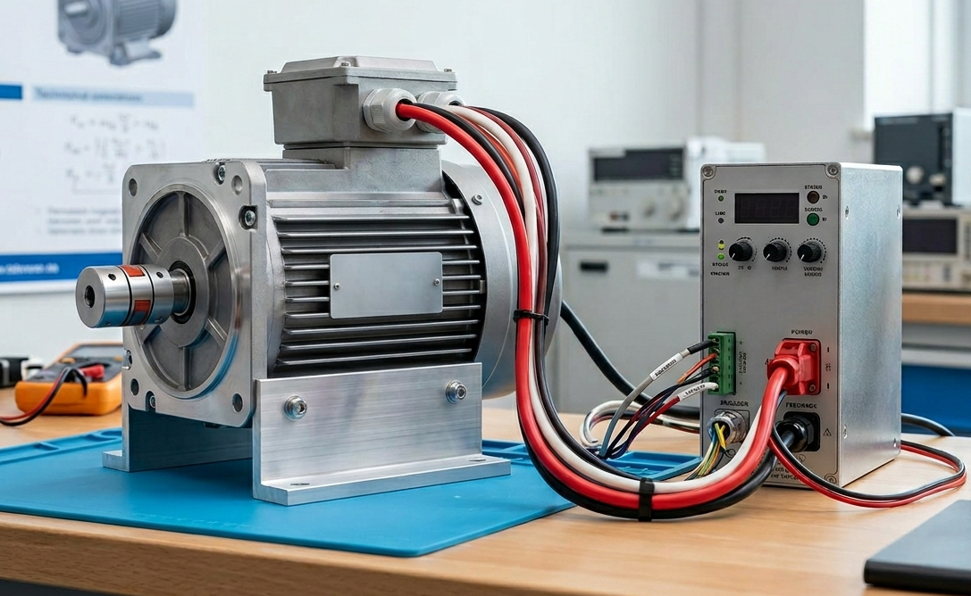
Photo by Simon Kadula on Unsplash
What happens when a classic PID controller competes against a Fuzzy Logic controller and a Sliding Mode Controller on exactly the same dynamic system?
That question became the starting point for a small engineering experiment: building a modular control-system simulation framework in C++ capable of testing multiple control strategies under identical conditions.
If you’re too hurry to take a look to the source code go to the following link: https://github.com/pablojoaquim/ControlLoopLab
The rules for this design were intentionally simple:
- the same plant
- the same disturbances
- the same timestep
- the same setpoint
- and only the controller changes
The goal was not to prove that one controller is universally “better” than the others, instead, understand how fundamentally different control philosophies behave when exposed to the exact same environment. In real-world control engineering, every strategy comes with strengths, weaknesses, assumptions, and tradeoffs.
To explore this, the framework implements three different Controllers for the same Plant (a simple brake hydraulic system):
- a classic PID controller
- a Fuzzy Logic controller
- and a Sliding Mode Controller (SMC)
Even before diving into the implementation details, the responses already tell an interesting story.

Some controllers react aggressively and converge quickly. Others prioritize smoothness and stability. Some handle disturbances gracefully, while others introduce oscillations or chattering effects.
What makes the comparison especially interesting is that all three controllers attempt to solve the same problem — but each one approaches it from a completely different perspective.
Before analyzing the simulation results, let’s briefly review how each controller works and the philosophy behind its design.
Modeling the Plant
Before comparing the controllers, the first step was defining a plant model representative of a simplified hydraulic brake system.
The simulation uses a classic second-order linear system, commonly used to model systems with inertia and damping:


This produces a slightly underdamped response — fast enough to feel realistic, while still allowing overshoot and transient dynamics to appear during testing.
Rather than using a simple step input, the setpoint was modeled as a brake pedal press-and-release profile (ramp up — hold — ramp down):

This makes the experiment significantly more interesting because controllers must handle both acceleration and release behavior, not just steady-state tracking.
The PID Controller
The Proportional-Integral-Derivative (PID) controller is the most widely used controller in industrial applications
The control law is straightforward:

Each term contributes differently:
- The proportional term reacts to current error. Higher Kp increases speed of response but can cause overshoot.
- The integral term eliminates steady-state error by accumulating past errors. High Ki causes windup and sluggish release.
- The derivative term anticipates future behavior. Adds damping and reduces overshoot.
For the simulation, the controller was tuned to prioritize fast tracking while avoiding excessive overshoot.
The resulting behavior was immediately recognizable:
- strong ramp tracking,
- small steady-state error,
- smooth response,
- but noticeable release lag during ramp-down.
That lag is largely caused by integrator windup. During the hold phase, the integral term accumulates energy that continues pushing the actuator even after the setpoint begins decreasing.

This is one of the most important characteristics of PID control: when properly tuned, it performs remarkably well on linear systems — but transient conditions and actuator saturation can expose its limitations quickly.
The Fuzzy Logic Controller
Unlike PID control, Fuzzy Logic Control does not require a precise mathematical model of the plant. In fact, this is one of the main reasons engineers choose this type of controller: in many real-world systems, we understand how the system should behave, but obtaining an accurate mathematical model is either extremely difficult or impractical.
Instead of relying on differential equations or complex mathematical models, Fuzzy Logic controllers encode human reasoning through a set of rules and linguistic descriptions of the system behavior. The tradeoff is complexity in a different form. While the mathematical modeling effort is reduced, the software design becomes significantly more challenging. The controller requires:
- membership functions or “adjetctives” that describe concepts such as “small error” or “large positive change”
- a carefully designed rule base capable of handling all operating conditions
- and extensive tuning of the linguistic ranges and normalization factors
In practice, defining these “adjectives” and tuning their interaction is often the hardest part of building a robust Fuzzy controller.

The rule base itself became one of the most interesting parts of the project because it effectively encodes the “driving style” of the controller.
IF error is PositiveBig
THEN control is PositiveBig

IF error is PositiveSmall
THEN control is PositiveSmall

IF error is Zero
THEN control is Zero
For the sake of simplicity, the simulation intentionally uses a very small and intuitive set of rules. Even with this minimal rule set, the controller already exhibits nonlinear and surprisingly natural behavior. Small positive errors generate soft control actions, while large positive errors produce more aggressive actuator commands. Negative or near-zero errors suppress braking effort entirely.
One of the most valuable aspects of the framework is how easy it becomes to iterate on these ideas. New rules, membership functions, and linguistic variables can be added with minimal changes to the simulation core, making the project a useful playground for experimenting with more advanced fuzzy strategies.
The result was a controller that felt smoother and more “human” during transitions, especially around the setpoint region.

Sliding Mode Control
Sliding Mode Control (SMC) was by far the most aggressive controller in the experiment.
Unlike PID or Fuzzy Logic, SMC is based on Variable Structure Control theory and introduces the concept of a sliding surface in the system state space. The controller continuously drives the system toward this surface using a switching control law.

The practical effect is dramatic:
- extremely fast convergence
- strong robustness
- excellent disturbance rejection
- but high-frequency switching near equilibrium
That switching behavior produces the well-known chattering phenomenon.
In the simulation, chattering appeared as a visible ripple during the hold phase — almost resembling ABS pressure cycling behavior in automotive systems.

What makes Sliding Mode Control especially interesting is how little information it requires compared to the performance it can achieve. Despite its mathematical elegance, the implementation itself remained surprisingly compact.
Building the Simulation Framework in C++
Once the controllers were defined, the next challenge was building a reusable simulation architecture capable of swapping controllers without modifying the plant model.
The framework was designed around a simple idea: Every controller should interact with the plant through the same interface.
This abstraction allowed controllers to be swapped without changing the simulation engine itself.

Each simulation step sleeps for 10 ms to match the Δt=0.01s step, providing visual real-time behavior in gnuplot. The gnuplot buffer is limited to 500 points (sliding window) to maintain rendering performance.
Abstracting the Controllers
Each controller exposes a common API through an abstract base class:
class IController
{
public:
    virtual double compute(double setpoint, double measurement, double dt) = 0;
    virtual void reset() = 0;
    virtual ~IController() = default;
};
Regardless of whether the implementation is a classical PID, a fuzzy inference engine or a nonlinear SMC controller the simulation engine interacts with them identically.
This greatly simplified experimentation because controllers became interchangeable components.
Abstracting the Plant
The plant model follows the same philosophy.
class IPlant
{
public:
    virtual double update(double input, double dt) = 0;
    virtual void reset() = 0;
    virtual ~IPlant() = default;
};
This separation between controller and plant turned out to be extremely valuable during development.
It allowed:
- testing multiple controllers on the same plant,
- validating behavior consistency,
- and experimenting with first-order and second-order systems without touching controller logic.
Smart Pointers
The framework relies heavily on std::shared_ptr to manage ownership dynamically.
std::shared_ptr<IController> pid = std::make_shared<PIDController>();std::shared_ptr<IPlant> plant = std::make_shared<SecondOrderPlant>();Using polymorphism together with smart pointers made the architecture flexible and easy to extend.
Controllers and plants can be selected at runtime without coupling the simulator to concrete implementations.
Results and Comparison
Once all three controllers were running under identical conditions, the behavioral differences became immediately visible.

The PID controller delivered stable and predictable performance, but showed clear release lag caused by integral accumulation.
The Fuzzy Logic controller produced smoother transitions and more natural damping behavior, although achieving that behavior required substantially more tuning effort.
The Sliding Mode Controller achieved the fastest convergence and strongest robustness, but introduced visible chattering near equilibrium.
Interestingly, none of the controllers was universally “best.”
And that was ultimately the most valuable result of the experiment: Not discovering a winner but understanding the tradeoffs.
메타데이터
- post_id
- 48f723051f6b
- slug
- pid-vs-fuzzy-logic-vs-sliding-mode-control-building-a-modular-c-simulation-framework-48f723051f6b
- url
- https://medium.com/@pablojoaquim/pid-vs-fuzzy-logic-vs-sliding-mode-control-building-a-modular-c-simulation-framework-48f723051f6b
- canonical_url
- https://medium.com/@pablojoaquim/pid-vs-fuzzy-logic-vs-sliding-mode-control-building-a-modular-c-simulation-framework-48f723051f6b
- author_url
- https://medium.com/@pablojoaquim
- status
- ok
- fetched_at
- 2026-06-09 15:37:30